Connect the power supply alarm, Connect the power supply alarm -8 – Verilink AS2000: The Basics (880-502981-001) Product Manual User Manual
Page 54
Hardware Installation
4-8
Verilink Access System 2000: The Basics
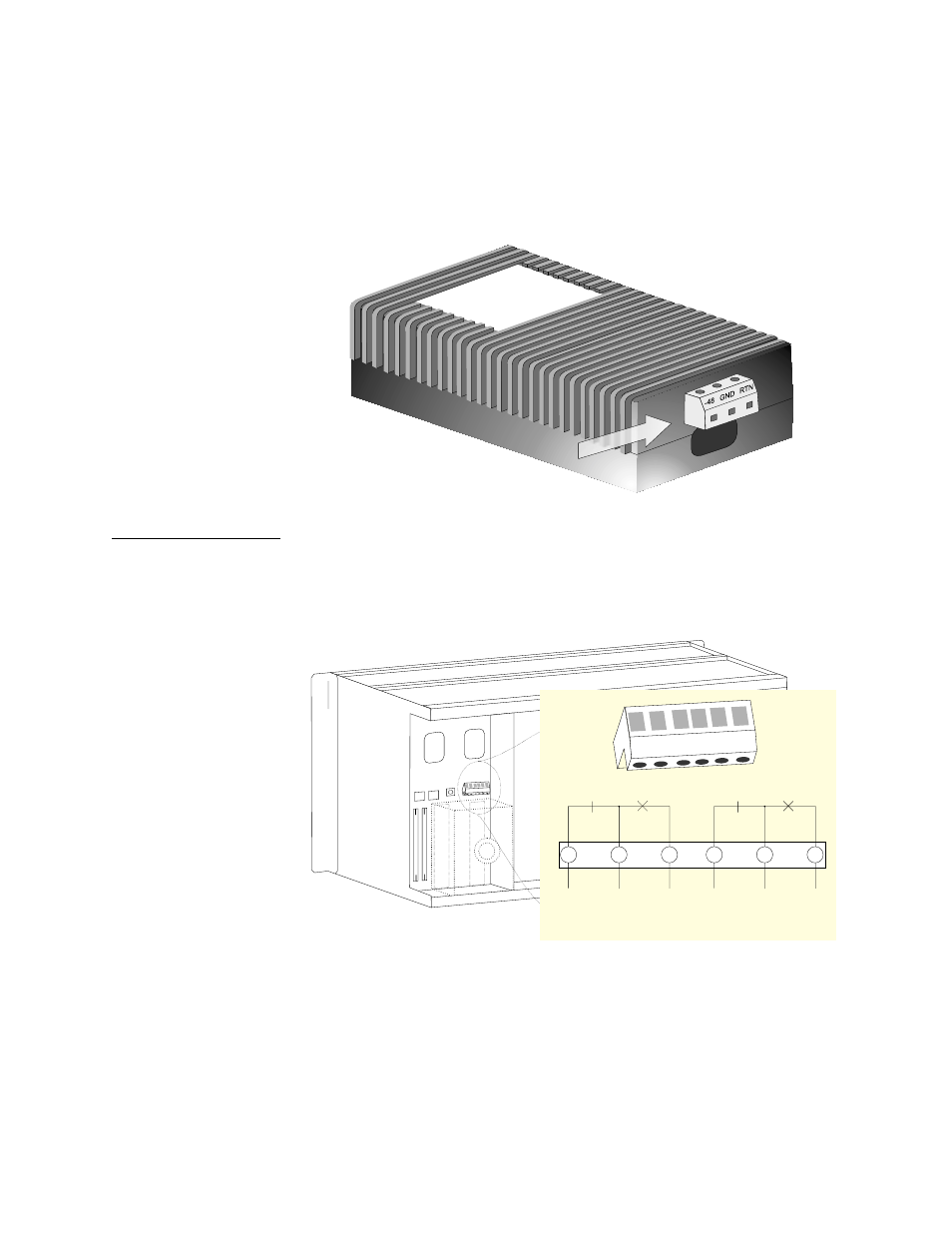
2. Insert the positive wire into the RTN socket of the DC input
connector, and tighten.
3. Insert the ground wire into GND socket and tighten.
4. Install the fuse when all connections are made.
Figure 4-7
PWR 2940 DC Input Connector
Connect the
Power Supply
Alarm
Connect the power supply alarm relay contacts from P3 (POWER
SUPPLY ALMS) on each Multi-line shelf to the office alarm
equipment. Refer to
.
Figure 4-8
Power Supply Alarm Relay Contact Wiring
A normally closed (NC) contact, a normally open (NO) contact, and a
common (COM) lead are provided for each power supply. Applying
power activates the NO and NC contacts. When power to the
equipment is lost or a power supply fails, the relay deactivates,
forcing the NO contacts closed and the NC contacts open. Connect
COM to NC or NO, depending on your office equipment. Torque
connector wire set screws to 4.5 to 8.0 inch lb (0.5 Nm to 0.9 Nm).
NC COM NO NC COM NO
NC
COM
NO
Supply A
Alarm
NC
COM
NO
Supply B
Alarm
- 1061 T1 Multicast (34-00268) Product Manual (18 pages)
- 2010 (34-00204) Product Manual (15 pages)
- 1558A (34-00228) Product Manual (39 pages)
- 1558D (34-00255) Product Manual (42 pages)
- 210 (34-00196) Product Manual (9 pages)
- 2000 (34-00182) Product Manual (58 pages)
- 300 (34-00199) Product Manual (9 pages)
- 2048 (34-00179) Product Manual (33 pages)
- 400 (34-00222) Product Manual (9 pages)
- 2100 (34-00187) Product Manual (19 pages)
- 7200p Series IAD (34-00334.B) Product Manual (311 pages)
- APS 2000 T1 Line Protection (880-502411-001) Product Manual (87 pages)
- AS200 (896-502379-001) Product Manual (112 pages)
- AS420 (34-00294) Product Manual (28 pages)
- AS56/56Plus (896-502588-001) Product Manual (130 pages)
- 9000 Series (34-00271) Product Manual (440 pages)
- Access Manager 2000 (896-502037-001) Product Manual (400 pages)
- ConnecT 56K DSU (896-502110-001) Product Manual (88 pages)
- AS4000 (34-00244) Product Manual (210 pages)
- C150 (880-502893-001) Product Manual (135 pages)
- Craft Interface (No Part Number) Product Manual (8 pages)
- DDS Lite (34-00295.C) Product Manual (19 pages)
- DCSU 2911 (880-502647-001) Product Manual (79 pages)
- DIDCSU 2912 (880-502646-001) Product Manual (107 pages)
- DIU 2130 (880-503297-001) Product Manual (101 pages)
- DIU 2131 (880-502765-001) Product Manual (31 pages)
- FrameStart FSE (34-00291.F) Product Manual (49 pages)
- DPRI 2922 (880-503142-001) Product Manual (91 pages)
- HDM 2180 (880-503048-001) Product Manual (79 pages)
- HDM 2182 (880-502925-001) Product Manual (81 pages)
- IMUX (880-503137-001) Product Manual (48 pages)
- FrameStart FSM (34-00299.E) Product Manual (153 pages)
- TAC 2010 (880-503298-001) Product Manual (65 pages)
- M1-3 (880-503136-001) Product Manual (75 pages)
- NCC 2130 (880-503285-001) Product Manual (61 pages)
- NCM 2000 (880-502623-001) Product Manual (91 pages)
- NetPath 2000 Product Manual (30 pages)
- PRISM 3000 (34-00184) Product Manual (45 pages)
- PRISM 3001 (34-00186) Product Manual (58 pages)
- PRISM 3002 (34-00277) Product Manual (52 pages)
- Net Engine (3150-30626-001) Product Manual (323 pages)
- PRISM 3021 (34-00262) Product Manual (47 pages)
- PRISM 3010 Dual DSX-1 (34-00250.2) Product Manual (22 pages)
- PRISM 3060-10 (34-00252.4) Product Manual (76 pages)