Daisy-chaining for the ncm, Extend, Daisy-chaining for the ncm -19 – Verilink AS2000: The Basics (880-502981-001) Product Manual User Manual
Page 65
Hardware Installation
Verilink Access System 2000: The Basics
4-19
2. If the node has more than one shelf, assign addresses 2, 3, and
4 to the additional shelves. No other address assignments are
valid.
3. Power cycle the shelf.
NOTE: The Quint-line shelf address can not be set. The default
address is always 1.
Extending the
TABs Node
Controller Bus
The RS-485 controller bus cable extends communication from the
NCC or SCC node controller to shelves containing other TABS-based
modules in the node.
1. Connect one end of the cable into the Controller Bus Out jack
on the first shelf, into the Controller Bus In jack on the second
shelf. Refer to
.
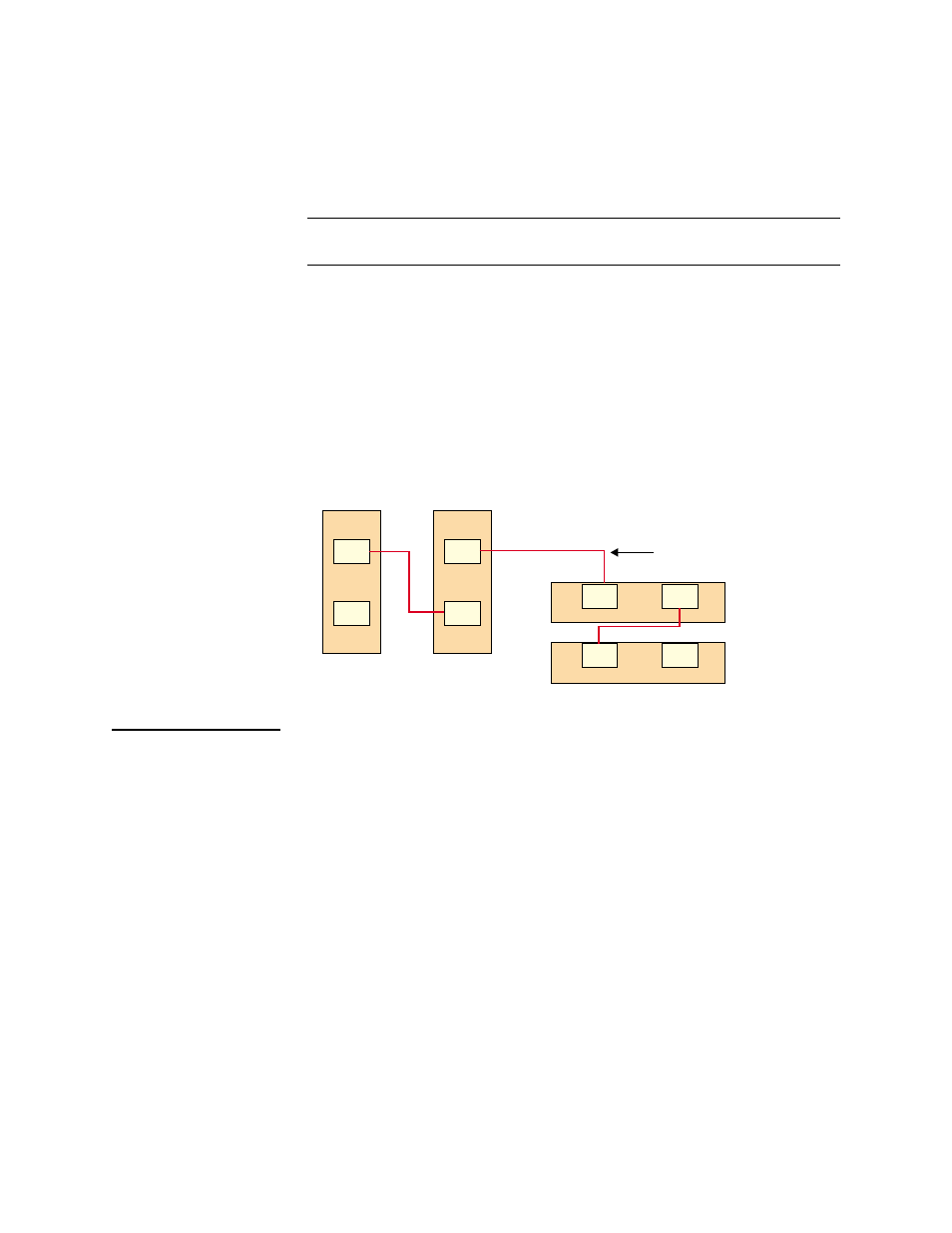
Figure 4-17 Expanding the TABs Controller Bus
Daisy-Chaining
for the NCM
The NCM uses the RJ-45 controller bus cable (Verilink part number
458-502313-008) to extend communication to shelves containing
other ACP-based modules in the node.
The EXT management port of the NCM is used to extend the ACP
bus to multiple shelves. Backplane cable connections are used to
extend the TABS bus. The example shown in
consists of
four shelves.
J4
J3
J4
J3
Bus In
Bus In
Bus Out
Bus In
Bus Out
Bus Out
Bus In
Bus Out
Multi-line shelf
# 1 (address 1)
Multi-line shelf
# 2 (address 2)
Dual-line shelf #1
(address 3)
Dual-line shelf #2
(address 4)
RJ-11 node
controller
bus cable
(Shown between each
pair of shelves)
J17
J16
J17
J16
J4
J3
J4
J3