J15 j14 – Verilink AS2000: The Basics (880-502981-001) Product Manual User Manual
Page 61
Hardware Installation
Verilink Access System 2000: The Basics
4-15
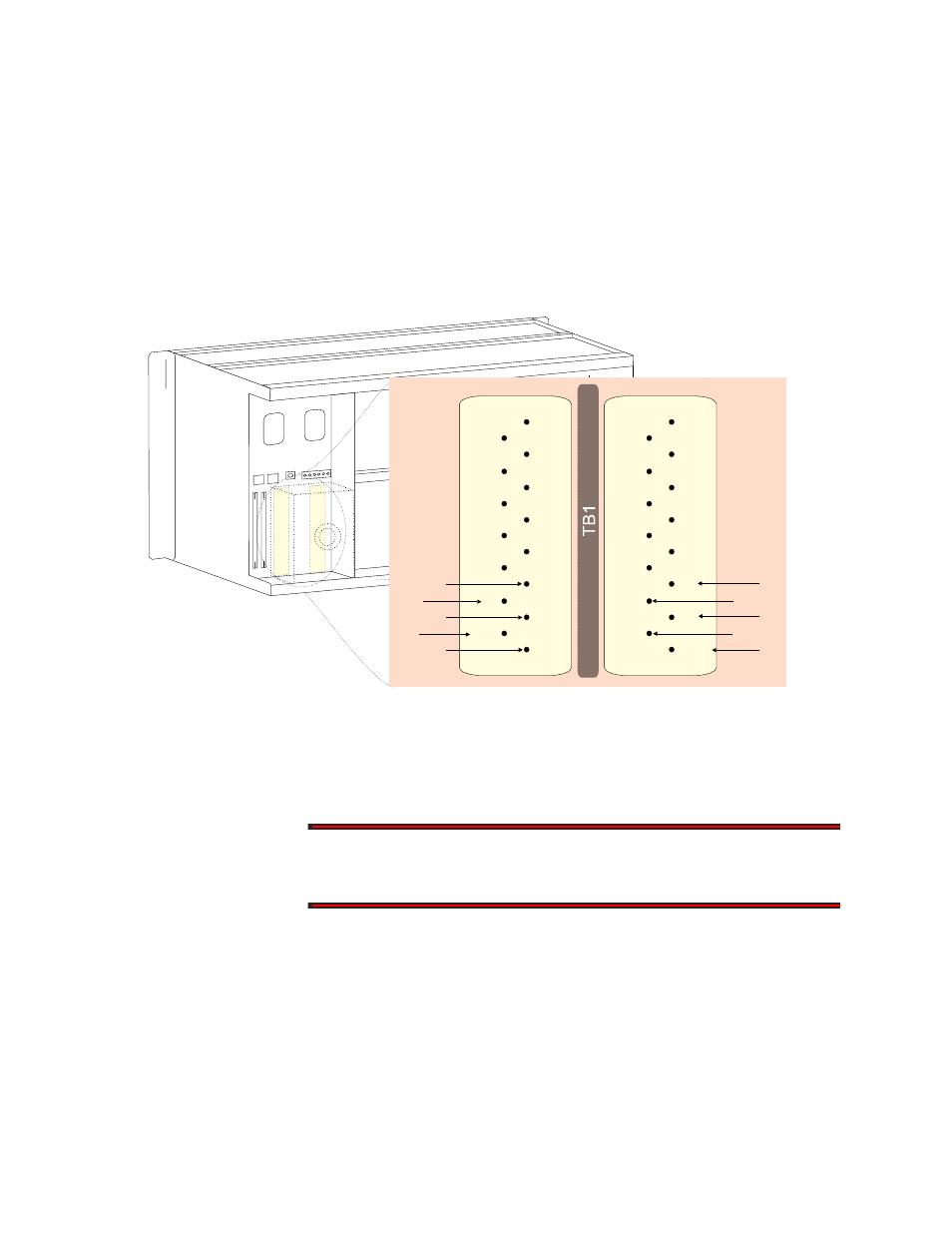
6. Measure the +5 VDC output on the front panel of the power
supply between the test points labeled, +5V and +5 RTN
(return). The reading should be +5.5V with a variance of
±0.055V. If the reading exceeds this variation in tolerance,
replace the power supply.
7. Unplug Power Supply A from the shelf, and repeat steps 1
through 4 above for Power Supply B. Install this power supply
into the second power unit slot next to Power Supply A.
Figure 4-14 Multi-line Ground and Voltage Measurements
8. Re-insert Power Supply A into the shelf.
9. Repeat Steps 1 through 6 for the remaining Multi-line shelves
in each node.
WARNING
To prevent possible arcing damage, re-install the protective cover box
over terminal strip TB1 before applying power.
Applying AC Power
to 115 VAC Power
Supplies (PAC
2910)
To apply power to the Multi-line shelf, do the following:
1. Plug one of the 115 VAC power supplies into the associated AC
outlet.
2. Verify that the Power LED is green on the power supply front
panel. If the LED is not lit, verify the voltage at the AC power
outlet.
-48 RTN A
NO_A
NC_A
GND
-12A
GND
GND
CGND
12 RTN
+5 A
-48 RTN B
-48 VB
NO_B
NC_B
GND
-12 B
GND
GND
C_B
CGND
12 RTN
+5 B
+5 B
J15
J14
-48 VA
C_A
+5 A
Pin 26
Pin 24
Pin 28
Pin 30
Pin 32
Pin 26
Pin 24
Pin 28
Pin 30
Pin 32