Dce to dte timing -11 – Verilink AS2000: The Basics (880-502981-001) Product Manual User Manual
Page 27
System Information
Verilink Access System 2000: The Basics
2-11
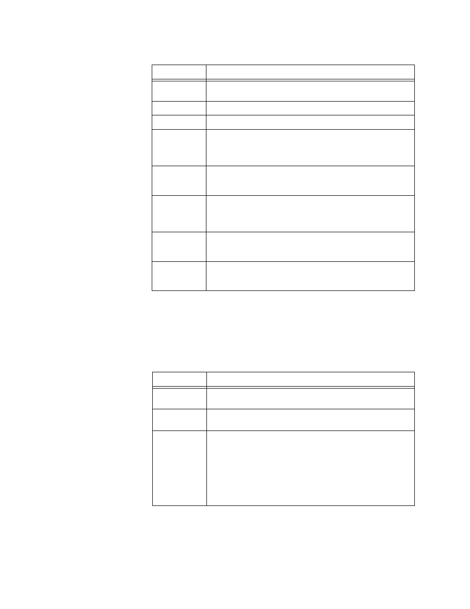
Table 2-5 CSU Timing
DCE to DTE Timing
The DSU provides transmit clock to the data equipment (for
example, the router), which present the next data bit to be sent.
DSUs have timing settings at their ports, and determine which part
of the clock pulse should be used when sampling received data
from the DTE. These choices are:
Table 2-6 DCE to DTE Timing Options
ST or inverted ST is determined by the data rate and length of
cabling between the DTE and DSU. Less than 1.3 Mbit/s generally
requires ST (fractional Level 1 service). Data rates greater than 1.3
Mbit/s usually require inverted ST. See
.
Options
Definition
Through
The DS1 or CEPT-1 equipment at this node provides clock.
(CSU, D&I)
Equipment
DS1 or CEPT-1 equipment provides clock. (D&I)
Internal
The CSU itself provides clock. (MUX, D&I)
External 422
The CSU is connected to an external RS-422 clocking device.
Network Service Provider (NSP) equipment (digital access
cross-connect switch or DACS) provides a balanced +/- signal
to the external clock. (MUX, D&I)
External TTL
The CSU connects to an external TTL (transistor-to-transistor
logic) clocking device. NSP equipment (DACS) provides an
unbalanced 0/+5 V signal to the external clock. (MUX, D&I)
Network
A DACS inside the NSP cloud, or the DCE or DTE at the far
end, provides the master clock. The CSU recovers clock from
the incoming network signal. Network timing is also
referred to as “recovered” or “slave” timing. (MUX, D&I)
TIU
A timing module (TIU 2850) within the node passes on the
clock signal it receives from another source. TIU supports
MUX, D&I modes for other products. (MUX, D&I)
DIU
The DIU passes the master clock, received from the data
equipment, to the CSU. Used with the Terminal Timing (TT)
setting (see “DCE to DTE Timing” in this chapter).
Options
Definitions
Send Timing
(ST)
The DSU samples the transmit data on the downward
(negative-going) edge of the transmit clock pulse.
Inverted ST
(INV ST)
The DSU samples the transmit data on the upward (positive-
going) edge of the transmit clock pulse.
Terminal
Timing (TT)
Used when the DTE has the capability to use the clocking
from the DSU signal and loop it around onto an optional
third clock pair. The third pair of wires is in addition to the
transmit clock and receive clock pairs. This clock may be
labeled TT, SCTE (Serial Clock Transmit External), or XTC
(eXternal Transmit Clock). The Terminal Timing option is the
preferred choice, because the clock is transmitted in phase
with the data, ensuring that samples are taken in the middle
of each bit.