Installing the rear connector module, Installing the application module, Installing the rear connector module -12 – Verilink AS2000: The Basics (880-502981-001) Product Manual User Manual
Page 58: Installing the application module -12
Hardware Installation
4-12
Verilink Access System 2000: The Basics
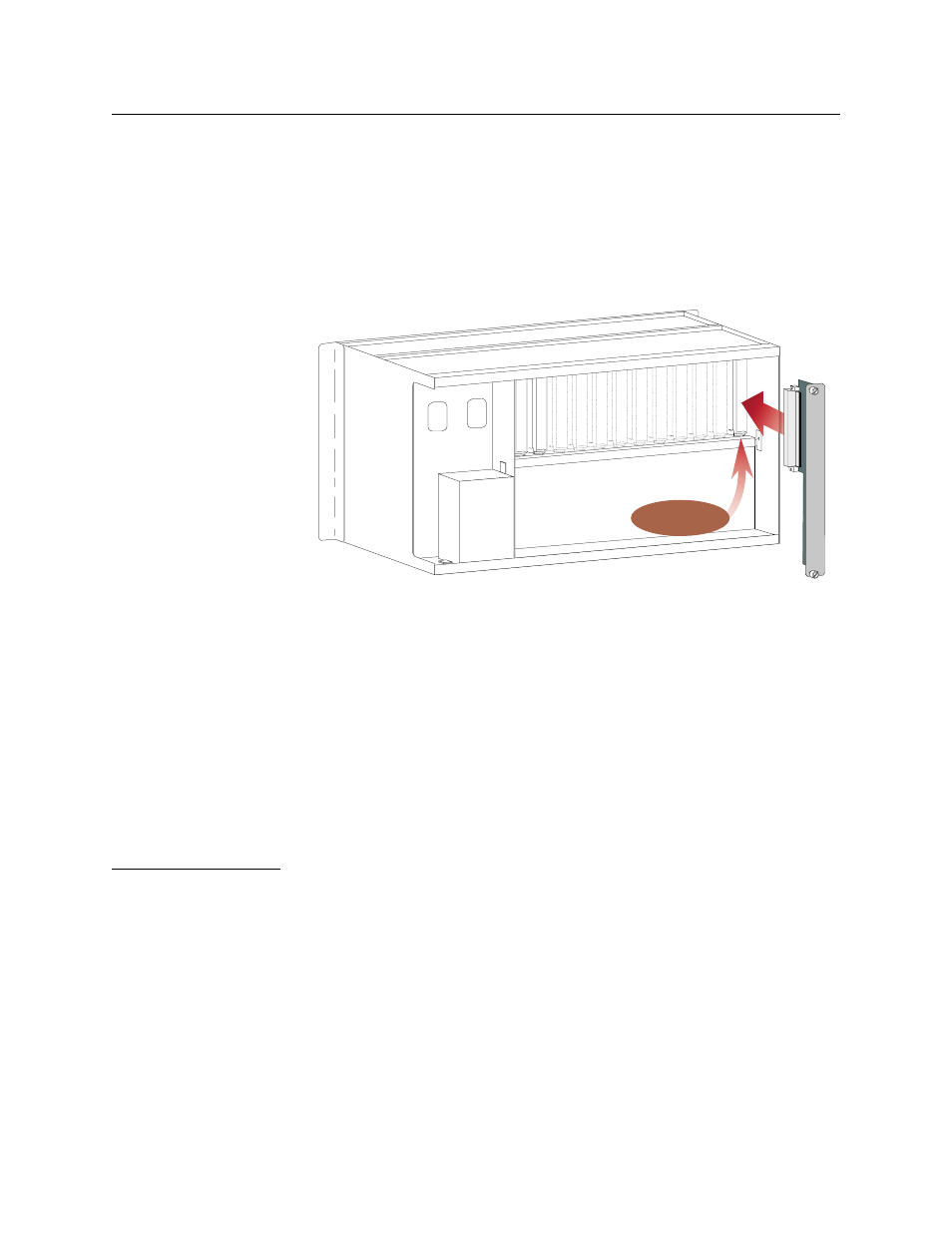
Installing the Rear Connector Module
Each rear connector module must be installed into the shelf before
its corresponding application module is installed. Refer to the
system configuration worksheet to match rear connector module to
its corresponding application module. If you are using an NCC or
SCC, it must occupy slot 1, shelf 1 in the system node.
illustrates a Multi-line shelf rear connector module installation.
Figure 4-11 Rear Connector Module Installation into a Multi-line Shelf
To install the rear connector modules, do the following:
1. Slide the rear connector module into the back of the assigned
shelf slot.
2. Verify the top and bottom of the connector module are flush
with the shelf.
3. Secure the rear connector module by tightening the two thumb
screws finger-tight on the ends of the panel.
4. Repeat the above procedure for each remaining rear connector
module.
Installing the
Application
Module
Slide each application module into its assigned slot until it seats in
the midplane. Position the ejector handles flush with the faceplate,
locking the application module into the shelf. See
Shelf Slot # 1