Crossover connection -12 – Verilink AS2000: The Basics (880-502981-001) Product Manual User Manual
Page 28
System Information
2-12
Verilink Access System 2000: The Basics
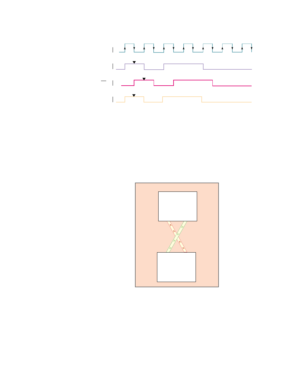
Figure 2-7
DCE to DTE Timing
Crossover
Connection
Use a crossover connection whenever transmit and receive signals
go to the opposite leads for an application, such as tail circuits.
The receive data from device A becomes the transmit data to device
B. The receive data from device B becomes the transmit data to
device A.
In a crossover circuit, each DCE relinquishes control of the transmit
path to the other DCE. Clock signals are also cross-connected. The
DCE device outputs receive data at the rate which data is received.
See
.
Figure 2-8
Crossover Connection
Synchronous devices output a receive clock that is in phase with
receive data. Since receive data becomes transmit data to the tail-
circuit DCE, it uses the receive clock from the main circuit DCE to
sample correctly. In most crossover connections, both devices are
configured to use the receive clock as the transmit clock. The CSU
and DSU timing settings depend on the location of the master
clock.
Clock
Signal
ST
TT
ST
DSU
rx rd
tt td
DSU
rx rd
tt td
- 1061 T1 Multicast (34-00268) Product Manual (18 pages)
- 2010 (34-00204) Product Manual (15 pages)
- 1558A (34-00228) Product Manual (39 pages)
- 1558D (34-00255) Product Manual (42 pages)
- 210 (34-00196) Product Manual (9 pages)
- 2000 (34-00182) Product Manual (58 pages)
- 300 (34-00199) Product Manual (9 pages)
- 2048 (34-00179) Product Manual (33 pages)
- 400 (34-00222) Product Manual (9 pages)
- 2100 (34-00187) Product Manual (19 pages)
- 7200p Series IAD (34-00334.B) Product Manual (311 pages)
- APS 2000 T1 Line Protection (880-502411-001) Product Manual (87 pages)
- AS200 (896-502379-001) Product Manual (112 pages)
- AS420 (34-00294) Product Manual (28 pages)
- AS56/56Plus (896-502588-001) Product Manual (130 pages)
- 9000 Series (34-00271) Product Manual (440 pages)
- Access Manager 2000 (896-502037-001) Product Manual (400 pages)
- ConnecT 56K DSU (896-502110-001) Product Manual (88 pages)
- AS4000 (34-00244) Product Manual (210 pages)
- C150 (880-502893-001) Product Manual (135 pages)
- Craft Interface (No Part Number) Product Manual (8 pages)
- DDS Lite (34-00295.C) Product Manual (19 pages)
- DCSU 2911 (880-502647-001) Product Manual (79 pages)
- DIDCSU 2912 (880-502646-001) Product Manual (107 pages)
- DIU 2130 (880-503297-001) Product Manual (101 pages)
- DIU 2131 (880-502765-001) Product Manual (31 pages)
- FrameStart FSE (34-00291.F) Product Manual (49 pages)
- DPRI 2922 (880-503142-001) Product Manual (91 pages)
- HDM 2180 (880-503048-001) Product Manual (79 pages)
- HDM 2182 (880-502925-001) Product Manual (81 pages)
- IMUX (880-503137-001) Product Manual (48 pages)
- FrameStart FSM (34-00299.E) Product Manual (153 pages)
- TAC 2010 (880-503298-001) Product Manual (65 pages)
- M1-3 (880-503136-001) Product Manual (75 pages)
- NCC 2130 (880-503285-001) Product Manual (61 pages)
- NCM 2000 (880-502623-001) Product Manual (91 pages)
- NetPath 2000 Product Manual (30 pages)
- PRISM 3000 (34-00184) Product Manual (45 pages)
- PRISM 3001 (34-00186) Product Manual (58 pages)
- PRISM 3002 (34-00277) Product Manual (52 pages)
- Net Engine (3150-30626-001) Product Manual (323 pages)
- PRISM 3021 (34-00262) Product Manual (47 pages)
- PRISM 3010 Dual DSX-1 (34-00250.2) Product Manual (22 pages)
- PRISM 3060-10 (34-00252.4) Product Manual (76 pages)