Acp data bus structure -3, Acp data bus structure – Verilink AS2000: The Basics (880-502981-001) Product Manual User Manual
Page 19
System Information
Verilink Access System 2000: The Basics
2-3
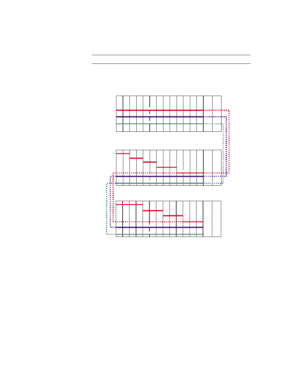
A5) is expanded to another shelf. Data bus extensions are only
supported by (non-IMUX) TABs-based modules, i.e. TAC 2010 and
DIU modules.
NOTE: The NCM does not support data bus extension.
illustrates the data bus configuration using the MLS 2000
and MLS 2200 series shelves.
Figure 2-2 AS2000 Data Bus Example
ACP Data Bus
Structure
The ACE architecture includes expanded data bus bandwidth,
enabling greater switching capacity between ACP modules. While
TABS-based modules have three 1.544 Mbit/s data buses—A, B, and
C—with ACE architecture, the B and C buses are 2.048 Mbit/s, and
the Bus A bandwidth is increased to 16.384 Mbit/s (8 E1 lines). The
total bandwidth available is 20.480 Mbit/s. Timeslot 0 of each ACP
bus A is used for framing. Bus A is divided into two sections,
designated as the low A bus and the high A bus. The low bus data
is sampled on the down stroke of the receive clock, and the high
bus data is sampled on the up stroke of the same clock.
2
3
4
5
6
7
8
9
10
11
12
13
1
Power
Supply
Power
Supply
A
B
Data Bus A
Data Bus B
Data Bus C
2
3
4
5
6
7
8
9
10
11
12
13
1
Power
Supply
Power
Supply
A
B
Data Bus B
Data Bus C
A1
A2
A3
A4
A5
Data Bus
Expansion
Cable
MLS2000
MLS2200
2
3
4
5
6
7
8
9
10
11
12
13
1
Power
Supply
Power
Supply
A
B
Data Bus B
Data Bus C
A1
A2
A3
A4
MLS2200-4i