Clock register a 0x1a, Clock register b 0x1b – Sundance SMT943 User Manual
Page 27
User Manual SMT943
Page 27 of 54
Last Edited: 23/08/2011 17:24:00
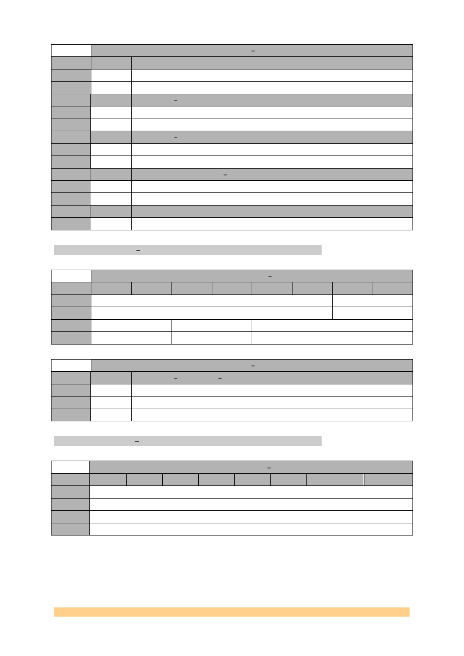
Reset Register 9 0x19
Setting
Bit 0
Description - Coarse Phase Adjustment[6] External Clock
0
0
1
1
Setting
Bit 7:1
Description Output Divider Ratio External Clock
0
0
1
1
Setting
Bit 8
Description Output Divider Enable External Clock
0
0
Divider disabled.
1
1
Divider enabled.
Setting
Bit 9
Description PECL4HISWING PECL output voltage swing (External Clock)
0
0
Normal Operation.
1
1
High PECL output voltage.
Setting
Bit 15:10
Description Output4 (External Clock) mode
0
0
LVPECL only: ‘100000’.
CLOCK Register A 0x1A.
Clock Register A 0x1A
Byte
Bit 7
Bit 6
Bit 5
Bit 4
Bit 3
Bit 2
Bit 1
Bit 0
1
Reserved
Reserved
Default
‘000000’
‘00’
0
Reserved
BIAS_DIV45
Reserved
Default
‘00’
‘00’
‘0101’
Reset Register A 0x1A
Setting
Bit 5:4
Description BIAS_DIV01 Current reduction output dividers 0 and 1
0
‘00’
No current output reduction
1
‘01’
20% output current reduction
2
‘10’
30% output current reduction
CLOCK Register B 0x1B.
Clock Register B 0x1B
Byte
Bit 7
Bit 6
Bit 5
Bit 4
Bit 3
Bit 2
Bit 1
Bit 0
1
Reserved
Default
‘01101000’
0
Reserved
Default
‘00000000’