B.3. configuring the ld2000 modbus communications, Configuring the ld2000 modbus communications, Figure b.4 zone configuration – RLE LD2000 User Manual
Page 67
www.rletech.com
67
970.484.6510
B
Leak Detection Modbus Master
B.3.
Configuring the LD2000 Modbus
Communications
Log into the LD2000 web interface and configure the unit to be a Modbus master:
1
From the Home page, click the Configuration link in the top bar. If using the EIA-485 port,
click on EIA-485 Port/Modbus/N2.
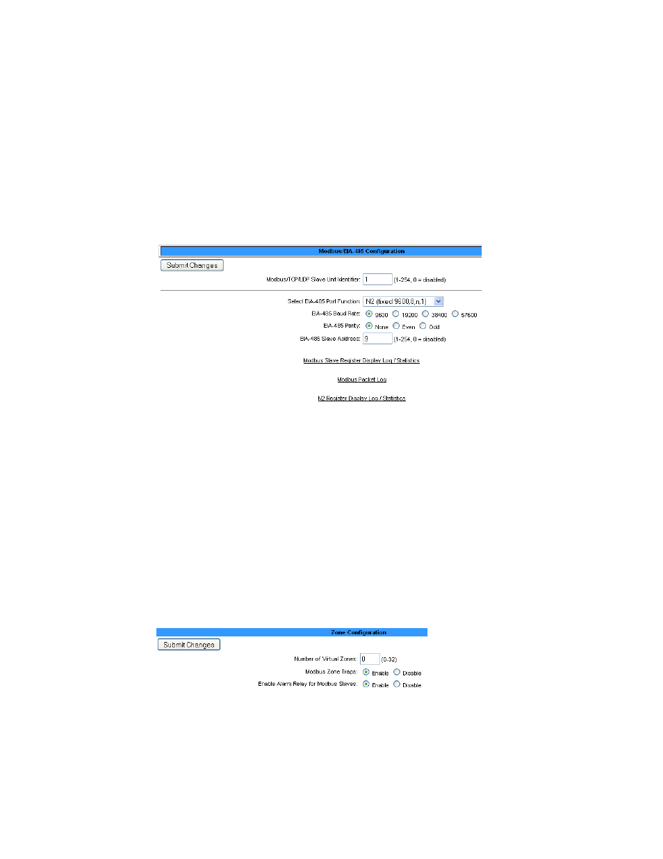
2
Once on the Modbus/EIA-485 Configuration page, select Modbus-Master or N2 from the
Select EIA-485 Port Function drop down. When completed, click on the submit changes
tab.
Figure B.3 Modbus/EIA-485 Configuration (Johnson N2 Shown)
Next, configure the slave units:
3
From the LD2000 Home page, click the Configuration link in the top bar. Choose from the
following options based on the configuration you want to set up:
a
To use addresses 2 through 8, choose
Zone Settings???
.
b
If using zones 1-8 for virtual zone labeling, use
Zone 9-16 Settings //what is this called
now?//
.
c
If you are not using the virtual zone feature, check the
Physical-Modbus/485
option.
Trap notifications can be enabled or disabled on individual units via the Modbus/EIA-
485 Configuration page. Click the submit changes button to save changes. Return to the
Configuration screen when finished.
Figure B.4 Zone Configuration