Packet communications for the ld2000, 1 function 03: read output registers, Function 03: read output registers – RLE LD2000 User Manual
Page 53: Table 5.2, Read output register packet structure, Table 5.3, Output registers
www.rletech.com
53
970.484.6510
5
Modbus Communication
5.2. Packet
Communications for the LD2000
This section covers the registers with the name and a brief description of each.
5.2.1 Function 03: Read Output Registers
To read the LD2000 parameter values, the master must send a Read Output Registers request
packet.
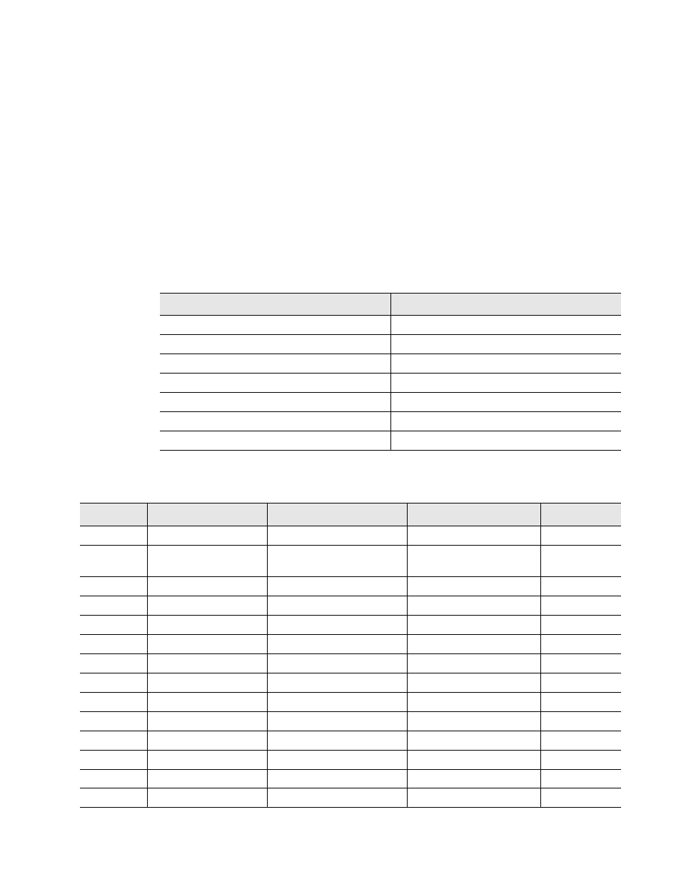
The Read Output Registers request packet specifies a start register and the number of registers
to read. The start register is numbered from zero (40001 = zero, 40002 = one, etc).
Table 5.2 Read Output Register Packet Structure
Read Registers Request Packet
Read Registers Response Packet
Slave Address (1 byte)
Slave Address (1 byte)
03 (Function code) (1 byte)
03 (Function code) (1 byte)
Start Register (2 bytes)
Byte count (1 byte)
# of registers to read (2 bytes)
First register (2 bytes)
Crc Checksum (2 bytes)
Second register (2 bytes)
…
Crc Checksum (2 bytes)
Table 5.3 Output Registers
Register
Name
Description
Units
Range
40001
Leak Threshold
Trip current for leak alarm
25-295 uAmps
0-65535
40002
Contamination
Threshold
Trip current for
contamination alarm
20-295 uAmps
0-65535
40003
Spare
0-65535
40004
Spare
0-65535
40005
Spare
0-65535
40006
Spare
0-65535
40007
Spare
0-65535
40008
Spare
0-65535
40009
Spare
0-65535
40010
Spare
0-65535
40011
Spare
0-65535
40012
Spare
0-65535
40013
Spare
0-65535
40014
Spare
0-65535