3 zone 1-8 settings, 4 network settings/ ip configuration, Figure 4.9 ip configuration – RLE LD2000 User Manual
Page 36
www.rletech.com
36
970.484.6510
4
Web Interface
4.3.3 Zone 1-8 Settings
Virtual Zones will display in the descriptions of any leak alarm when detected in the
appropriate cable range. Labeling zone descriptions increases the speed in which a leak is
physically discovered. For example, a section of cable located in the “Room A” might be
labeled “Rm. A.” Because the description refers to a familiar location rather than cable
distance, the alarm can be located faster. Each zone begins with previous zone's end distance
and ends with its own. Zone 1 begins at zero.
See Appendix B, “Leak Detection Modbus Master” on page 65 if using the LD2000 for Leak
Detection Modbus Master. Appendix B describes the Physical/Modbus/485 for settings 1-8
and settings 9-16.
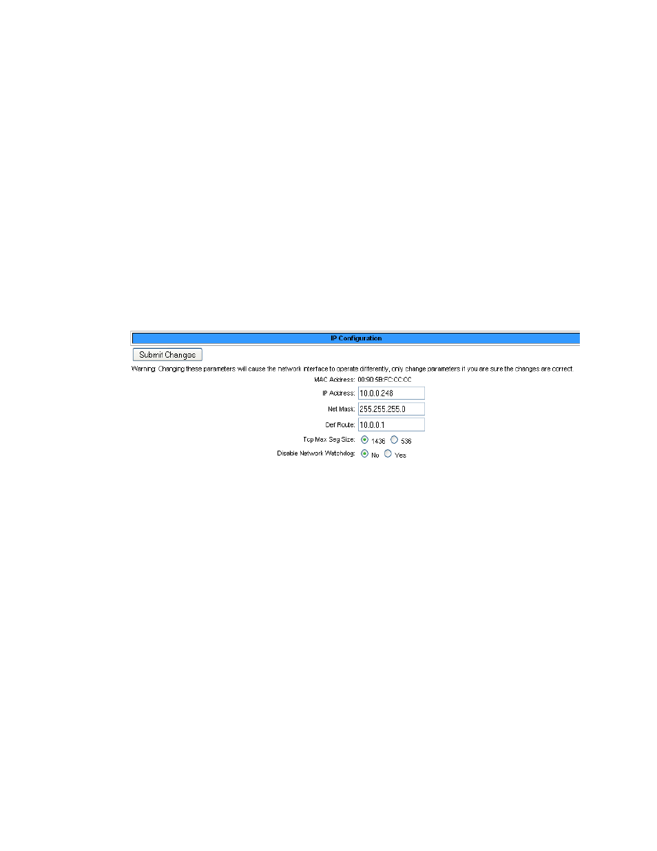
4.3.4 Network Settings/ IP Configuration
The Network settings allow users to change the network configuration of the LD2000. IP
address, Subnet Mask, and Default Route (Gateway) may be changed from this menu.
Figure 4.9 IP Configuration