2 function 04: read input registers, Function 04: read input registers, Table 5.4 – RLE LD2000 User Manual
Page 54: Read input registers packet structure, Table 5.5, Input registers
www.rletech.com
54
970.484.6510
5
Modbus Communication
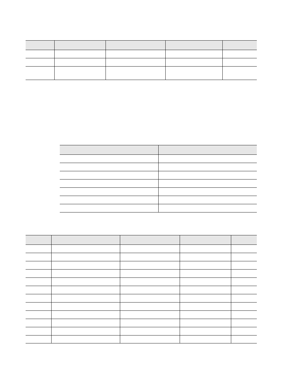
5.2.2 Function 04: Read Input Registers
To read the LD2000 input values, the master must send a Read Input Registers request packet.
The Read Input Registers request packet specifies a start register and the number of registers
to read. The start register is numbered from zero (30001 = zero, 30002 = one, etc).
40015
Spare
0-65535
40016
Leak Alarm Delay
Leak Alarm Delay
5-995 seconds
0-65535
40017
Contamination Alarm
Delay
Contamination Alarm
Delay
5-995 seconds
0-65535
Table 5.3 Output Registers (continued)
Register
Name
Description
Units
Range
Table 5.4 Read Input Registers Packet Structure
Read Registers Request Packet
Read Registers Response Packet
Slave Address (1 byte)
Slave Address (1 byte)
04 (Function code) (1 byte)
04 (Function code) (1 byte)
Start Register (2 bytes)
Byte count (1 byte)
# of registers to read (2 bytes)
First register (2 bytes)
Crc Checksum (2 bytes)
Second register (2 bytes)
…
Crc Checksum (2 bytes)
Table 5.5 Input Registers
Register
Name
Description
Units
Range
30001
Status
Bit level status
None
0-65535
30002
Leak Distance
Location of leak
Ft/Meters
0-65535
30003
Units
Unit of measure
1=Ft 0=Meters
0-65535
30004
Leak Current
Leakage current on cable
uAmps
0-65535
30005
Cable Length
Installed cable length
Ft/Meters
0-65535
30006
Loop1 Res
Resistance of cable
Ohms
0-65535
30007
Loop2 Res
Resistance of cable
Ohms
0-65535
30008
Res/Ft
Resistance of cable Ohms
x1000
0-65535
30009
Version
Firmware version
xx.xx X 100
0-65535
30010
Virtual Zone Alarm Status
Bit Level Status
None
0-65535
30011
Modbus Zone Enabled Flags
Bit Level Status
None
0-65535
30012
Modbus Zone2 Status
Bit Level Status
None
0-65535