REMKO HTS 90 ALU User Manual
Page 51
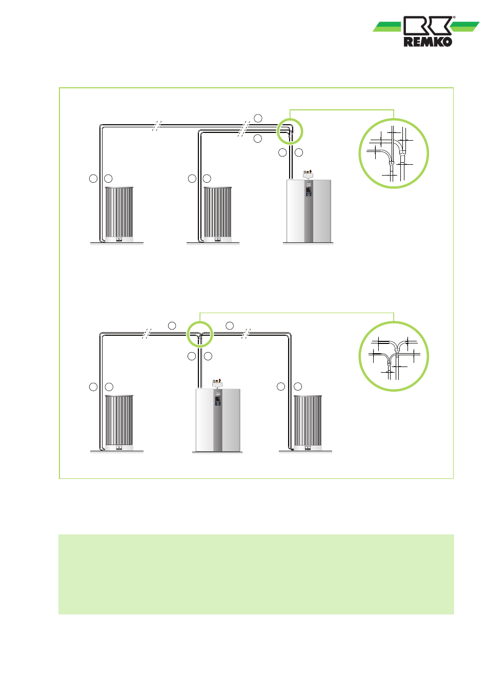
Dimensioning of the refrigerant piping based on the example of the HTS 200 series
A
B
A
1
A
2
B
1
B
2
1
2
1
2
A
2
B
2
3/4"
5/8"
5/8"
3/8"
3/8"
1/2"
A
1
B
1
3/4"
1/2"
3/8"
3/8"
5/8"
5/8"
A
B
Fig. 32: Connection options
A:
Refrigerant suction pipe 3/4"
A1,A2: Refrigerant suction pipe 5/8"
B:
Refrigerant inlet pipe 1/2"
B1,B2: Refrigerant inlet pipe 3/8"
1:
Line 1
2:
Line 2 - (
DP line 1
≈ DP line 2)
NOTES
1. The refrigerant piping 1 and 2 must have the same line length and cross-section.
2. To assure optimum refrigerant distribution in the line system, the T-pieces
must be installed as closed as possible to the indoor module.
3. With horizontal assembly of the refrigerant distributor (Y-piece) ensure that the distributor is only
ever installed in a horizontal position to assure uniform distribution of refrigerant and oil.
51