4 assembly, 1 system layout, Assembly 4.1 system layout – REMKO HTS 90 ALU User Manual
Page 34: Remko hts, 4assembly, Ab d c
4
Assembly
4.1 System layout
A
B
D
C
1
2
3
4
5
6
8
7
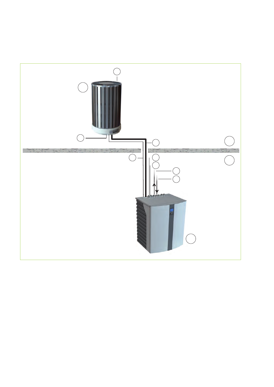
Fig. 12: System layout HTS 90 / HTS 130
A: Outdoor area
B: Indoor area
C: Outdoor module
D: Indoor module
1: Fan / air outlet
2: Condensate drain, external module
(must contain anti-freeze!)
3: Lines between indoor and outdoor modules /
condensate heating, ontrol wire (0-10V, e.g. 5 x 1 mm
2
),
power inlet 3 x 1.5 mm
2
,
sensor cable sheathed 2 x 1.0 mm
2
.
4: Refrigerant lines
3
/
8
" and
5
/
8
“
5: Inlet
6: Return flow
7: Power supply line to indoor module:
HTS 90= 230V / 1~ / 50Hz, 16A (e.g. 3 x 2.5 mm
2
)
HTS 130= 400V / 3~ / 50Hz, 3x16A (e.g. 5 x 2.5 mm
2
)
8: Mains supply line, electrical auxiliary heating =
400V / 3~ / 50Hz, 16A (e.g. 5 x 2.5 mm
2
)
REMKO HTS
34
This manual is related to the following products: