Remko hts – REMKO HTS 90 ALU User Manual
Page 44
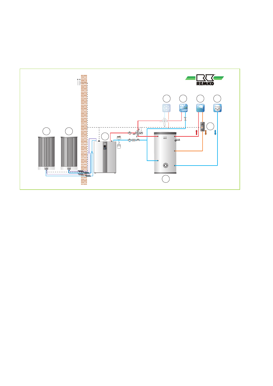
Hydraulic circuit diagram HTS 200/260
Functions: heating or cooling and hot water, operating mode: mono-energetic.
This hydraulic diagram serves merely to assist in planning activities;
the hydraulic system on site must be planned and laid out by the installer!
A1
B
1
2
3
C
4
5
EWS
A2
Schema_HTS_200_260_Stuttgart
Fig. 26: Example hydraulic diagram HTS 200/260
A1: Outdoor module 1
A2: Outdoor module 2
B:
Indoor module
C: Domestic hot-water tank
1:
Cooling cycle
2:
Mixed heating circuit
3:
Hot water
4:
Cold water
5:
Circulation
HTS compact heat pump models are ideal for use in new or in old construction, where the heat pump is the
sole heat generator. In an emergency, an electr. auxiliary heater (mono-energetic variant) can be switched
on by the Smart Control.
The highly efficient primary pump in the indoor unit can be used as a circulation pump heating cycle and its
speed is regulated. A pressure loss of max. 80 kPa is made available by the customer. If the pressure losses
on site exceed this, a separate storage tank, e.g. Remko KPS 300 must be used as a hydraulic compen-
sator. Then a Remko heating cycle group unmixed, type HGU, and a mixed heating cycle group, type HGM,
are available.
The Remko drinking water storage tank, type EWS 300E is an enamelled drinking water storage tank with a
HE surface area of 3.5m². The external additionally necessitated three-way changeover valve is switched
over by the Smart Control to provide HW.
REMKO HTS
44