Ab d c – REMKO HTS 90 ALU User Manual
Page 29
Water heat pumps require two wells to retrieve
heat from ground water, a suction well and a soak-
away well. The development of this source is not
possible everywhere. It is expensive and requires
planning permission.
Function of the heat pump
A heat pump is a device which makes use of a
working medium to absorb ambient heat under low
temperatures and transports this heat to a place
where it can be of use for heating purposes. Heat
pumps work according to the same principles as a
refrigerator. The difference is that heat, the by-
product of the refrigerator, is the goal of the heat
pump.
The main components of the cooling circuit consist
of an evaporator, a compressor, a condenser and
an expansion valve. In a finned evaporator, the
refrigerant evaporates both because of lower pres-
sure and because of lower heat-source tempera-
tures through absorption of energy from the envi-
ronment. In the compressor, the refrigerant is
brought to a higher pressure and temperature by
the application of electrical energy. Next, the hot
refrigerant gas reaches the condenser, a plate
heat-exchanger. Here the hot gas condenses,
transferring heat to the heating system. The lique-
fied refrigerant then expands and cools in a flow
regulator, the expansion valve. Then the refrig-
erant flows into the evaporator once more and the
cycle is complete.
For control, Smart-Control is employed, and it
assures the independent operation of all safety
devices. The water-circulation system of the indoor
module HTS consists of a charging pump, plate
heat-exchangers, dirt traps, compressor, electrical
expansion valve, safety valve, pressure gauge, fill-
and drain valves, an automatic air-bleeder and flow
monitor. The outdoor module contains the evapo-
rator and a speed-controlled and highly efficient
fan. The HTS 90 series has an outdoor module,
while series HTS 130 and series HTS 200 each
have 2 outdoor modules.
Wall- and floor consoles, condensate pans, con-
densate-pan heating, a 3-way switching valve, a
bypass valve and other sensors are available as
accessories.
2
1
4
3
A
B
D
C
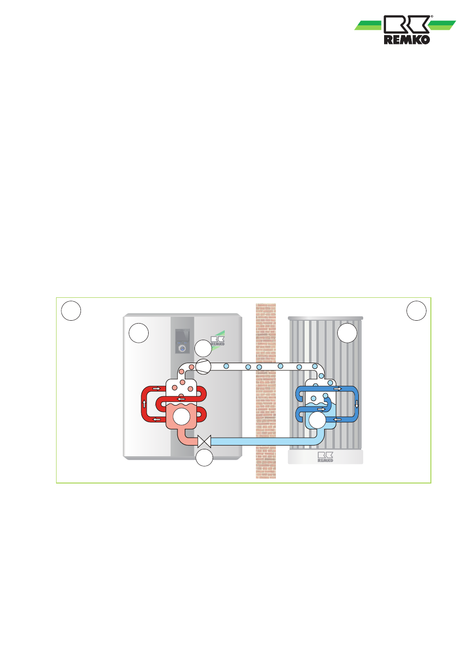
Fig. 8: Function diagram for heating the inverter heat pump
A: Indoor area
B: Outdoor area
C: Heat pump indoor module
D: Heat pump outdoor unit
1: Condensing
2: Liquefying
3: Decompression
4: Evaporation
29