Ab d – REMKO HTS 90 ALU User Manual
Page 35
A
B
D
1
2
3
5
6
8
7
C
1
C
2
1
2
4
4
3
9
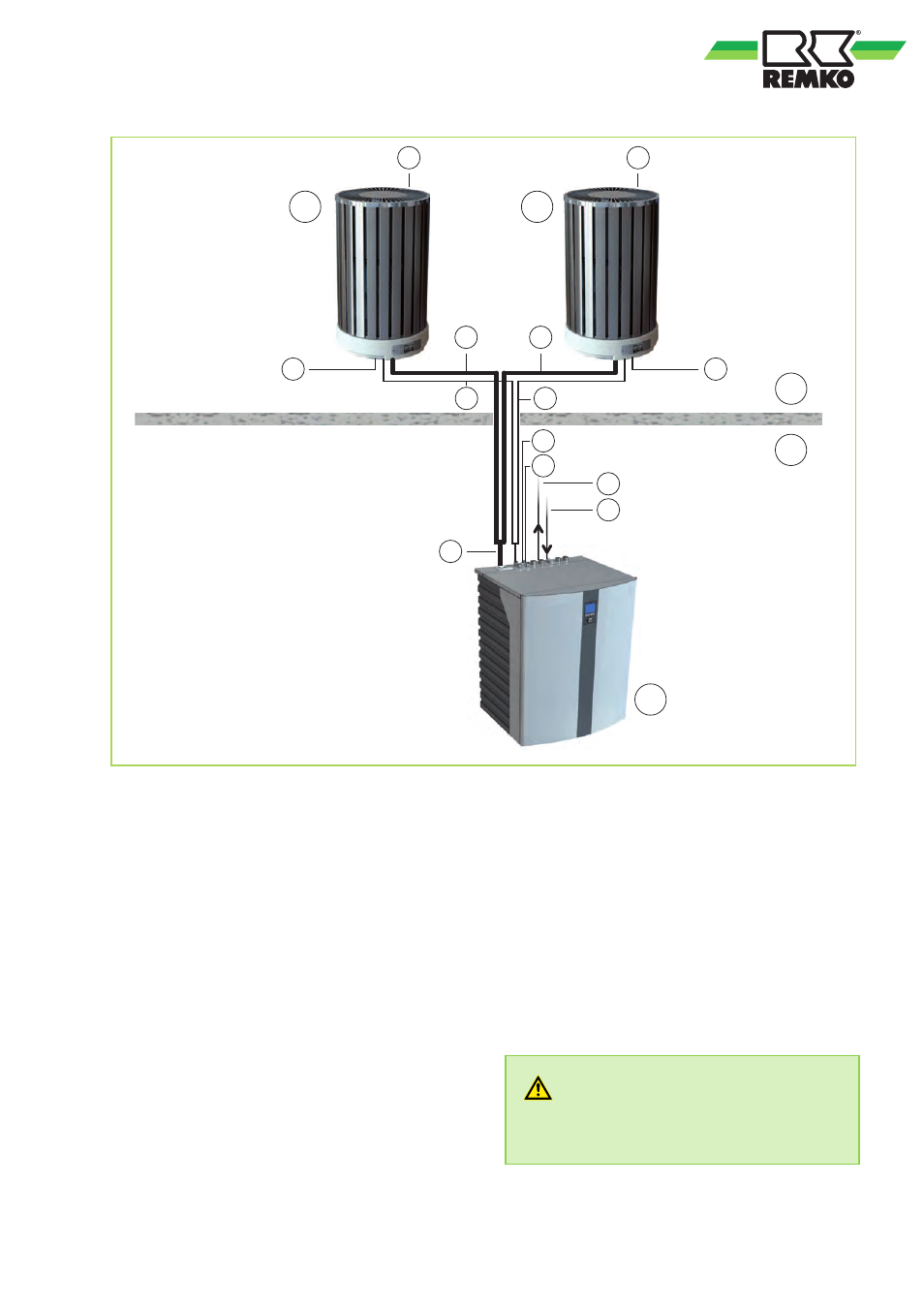
Fig. 13: System layout HTS 200 / HTS 260
A:
Outdoor area
B:
Indoor area
C1: Outdoor module 1
C2: Outdoor module 2
D:
Indoor module
1:
Fan
2:
Condensate drain, external module
(must contain anti-freeze!)
3:
Lines between indoor and outdoor modules /
condensate heating, control wire (0-10V, e.g. 5 x 1 mm
2
),
power inlet 3 x 1.5 mm
2
,
sensor cable sheathed 2 x 1.0 mm
2
.
4:
Refrigerant lines
3
/
8
" and
5
/
8
“
5:
Inlet
6:
Return flow
7:
Mains supply line, indoor module =
400V / 3~ / 50Hz, 16A (e.g. 5 x 2.5 mm
2
)
8:
Mains supply line, electrical auxiliary heating =
400V / 3~ / 50Hz, 16A (e.g. 5 x 2.5 mm
2
)
9:
Refrigerant line 1/2" and 3/4"
The indoor and outdoor modules have to be con-
nected with refrigerant lines of dimensions (outer
diameter)
3
/
8
"(=9.52 mm) and
5
/
8
"(=15.88 mm). At
least a two-wire control cable has to be laid
between the two modules. Both the indoor and out-
door modules require a separate power supply.
WARNING!
All electric lines are in accordance VDE regula-
tions to dimension and to lay.
35