OWON MSO Series User Manual
Page 32
27
from input signal. See Fig.5-2.
Press F1 again to set "DC" mode, both AC and DC components get passed.
See Fig.5-3.
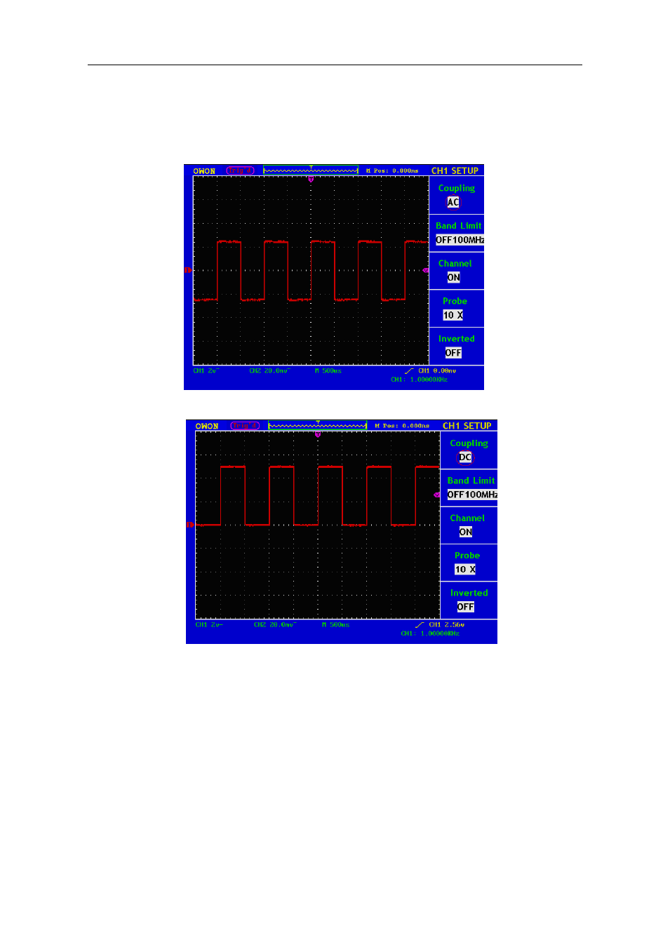
The wave forms are shown as Fig.5-2 and Fig.5-3.
Fig. 5-2 AC Coupling Oscillogram
Fig. 5-3 DC Coupling Oscillogram
2.
Setting the "Band Limit"
Taking the Channel 1 for example, the operation steps are shown as below:
(1). Press the CH1 MENU button and call out the CH1 SETUP menu.
(2). Press the F2 menu selection button and select the Band Limit as OFF
100MHz, with Channel 1 Band Limit switched off.
(3). Press F2 menu selection button again, select the Band Limit as ON 20MHz,
with Channel 1 Band Limit is switched on.
3.
Setting the Channel "ON/OFF"