Appendix a a, Digital488/80a hvcx1 configuration record, Record…… 81 – Measurement Computing Digital488/80A User Manual
Page 87: Re setup…… 81
Appendix A
A
Digital488/80A HVCX1 Configuration Record…… 81
Hardware Setup…… 81
Software Setup…… 82
DB-50 Connector Wiring Reference…… 83
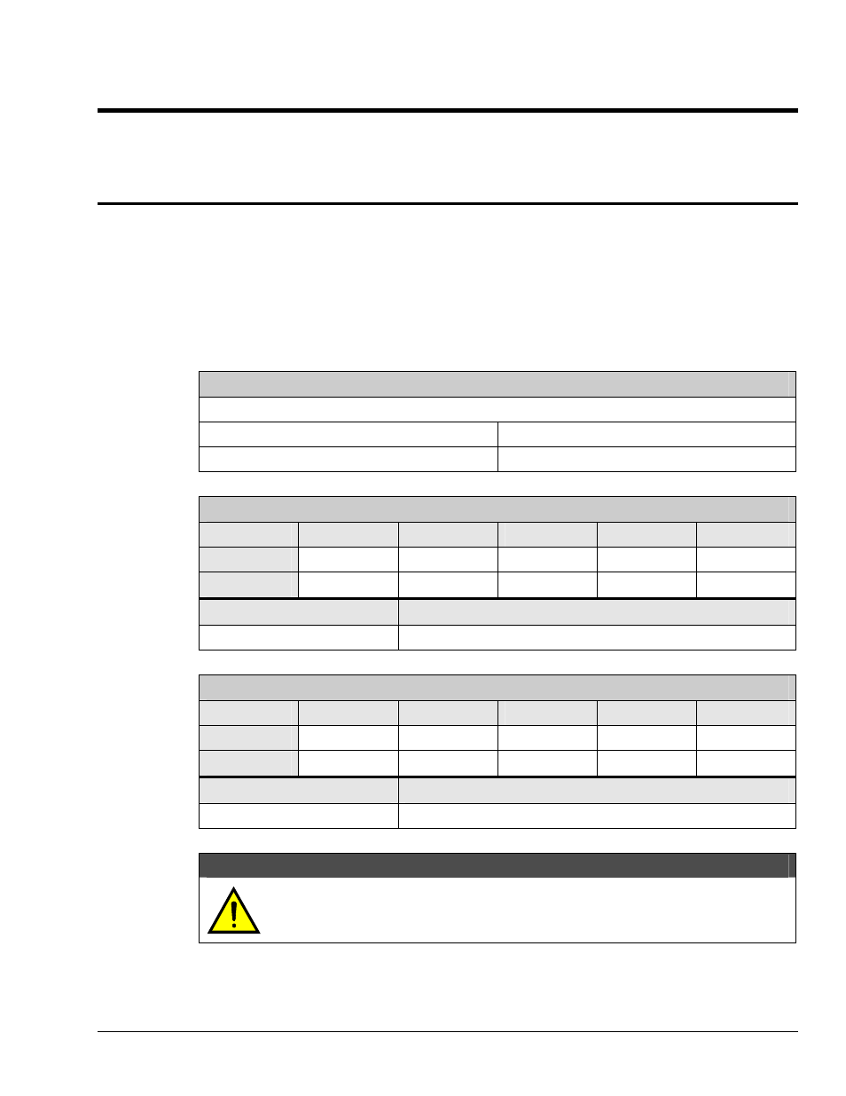
Digital488/80A HVCX1 Configuration Record
To use this Configuration Record, check the boxes for the options configured. Where appropriate, write in
the voltage value selected. A wiring reference chart for each channel is provided for recording the
equipment wired to the DB-50 connectors.
Make a copy of this blank form or write in pencil so future changes can be recorded.
Hardware Setup
Refer to the section "Hardware Setup" in Chapter 2: Digital488/80A Setup.
IEEE 488 Bus Addressing
U Dual Primary, or U Secondary
Channel 0 Address: ___ ___
Channel 0 Address: ___ ___ ___ ___
Channel 1 Address: ___ ___
Channel 1 Address: ___ ___ ___ ___
Channel 0
Port 1
Port 2
Port 3
Port 4
Port 5
Inputs
U _______V
U _______V
U _______V
U _______V
U _______V
Outputs
U
U
U
U
U
Pin 48 (Flyback/Pull-Up)
Control (Output Handshaking Lines)
U _______V
U +5 VDC, or U User Defined _______V
Channel 1
Port 1
Port 2
Port 3
Port 4
Port 5
Inputs
U _______V
U _______V
U _______V
U _______V
U _______V
Outputs
U
U
U
U
U
Pin 48 (Flyback/Pull-Up)
Control (Output Handshaking Lines)
U _______V
U +5 VDC, or U User Defined _______V
CAUTION
The hardware and software configurations for the input and output ports must agree.
The Digital488/80A unit is protected from configuration conflict, but the I/O lines will
not respond properly.
Digital488/80A User’s Manual
Appendix A 81