Ode…… 8 – Measurement Computing Digital488/80A User Manual
Page 14
Dual Primary Addressing Mode
The Digital488/80A can be thought of as two identical IEEE 488-to-digital I/O interfaces. Each interface
occupies one bus address and has one I/O channel. For this reason the Digital488/80A occupies two bus
addresses in an IEEE 488 system.
The default addressing mode on the Digital488/80A is "Dual Primary,” in which two consecutive bus
addresses are used. Dual Primary addressing offers ease of use at the expense of two bus address
locations. This may not be practical for applications in which the bus address locations are required by
other equipment. In these situations, “Secondary" addressing mode may be used. Secondary addressing
uses a single bus address for multiple interfaces.
When Dual Primary addressing mode is selected with DIP microswitch 8 in the "up" position, then
microswitch 1 (LSB of the address) is ignored. The Channel 0 interface resides at an even numbered bus
address, while the Channel 1 interface resides at the next higher odd address. For example, if the address
switches are set for IEEE 488 bus address 8, Channel 0’s interface resides at bus address 8 and Channel 1’s
interface resides at bus address 9.
Note:
Because the IEEE 488 standard has reserved address 31, if address 30 is selected when in Dual
Primary addressing mode, then the Digital488/80A defaults to address 28 for Channel 0, and to
address 29 for Channel 1.
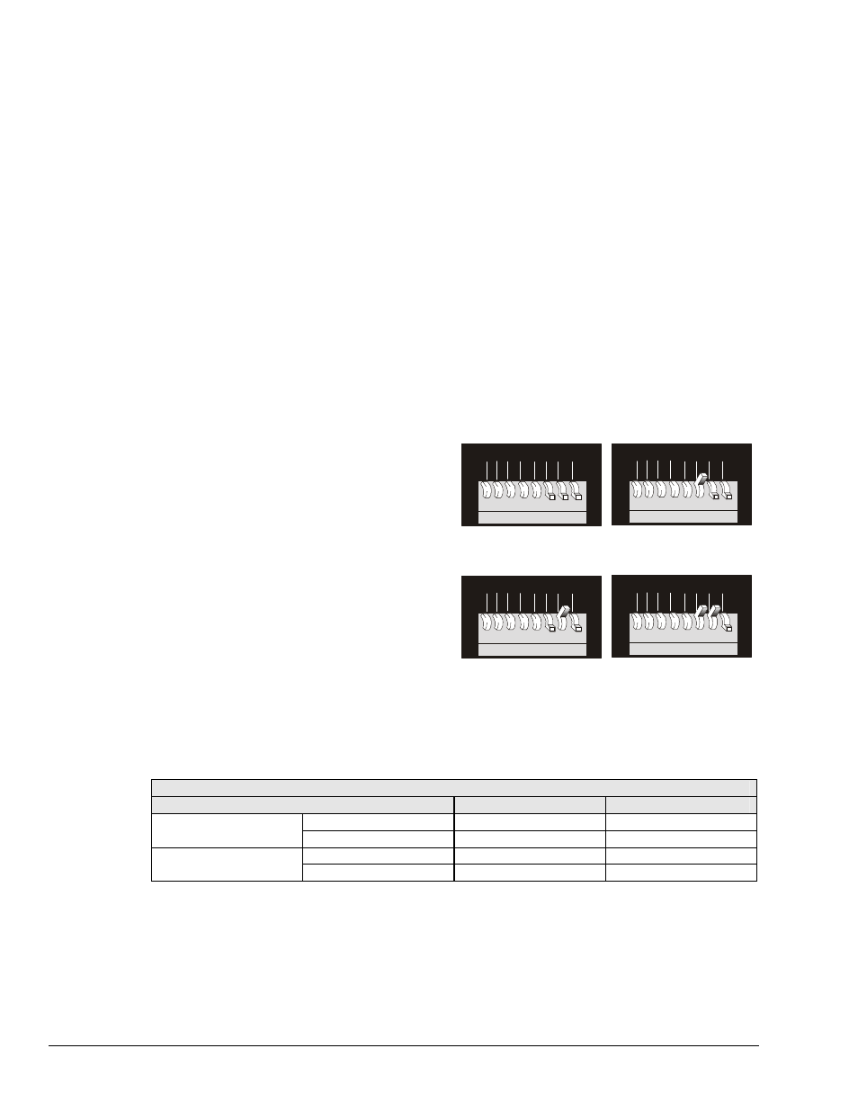
Secondary Addressing Mode
When Secondary addressing mode is selected with
DIP microswitch 8 in the "down" position, then up
to four Digital488/80A units can reside at the same
primary bus addresses. The Secondary addresses
at which Channel 0 and Channel 1 reside, are
selected with microswitches 6 and 7, as indicated
in the adjacent figure.
Note:
When in the Secondary address mode, if
IEEE 488 primary address 31 is selected,
the Digital488/80A unit will
automatically default to primary address
30.
For example, if two Digital488/80A units are
configured for primary address 08, with the first
unit being configured for Secondary addresses 0
and 1, and the second unit configured for
Secondary addresses 2 and 3, then the
communication is as indicated by the following
table.
1
1
1
1
2
2
2
2
4
4
4
4
8
8
8
8
16
16
16
16
x
x
x
x
y
y
y
y
D/S
D/S
D/S
D/S
6 7 8
6 7 8
6 7 8
6 7 8
5
5
5
5
2 3
2 3
2 3
2 3
1
1
1
1
1
0
1
0
1
0
1
0
4
4
4
4
Addresses 0 and 1
Addresses 4 and 5
Addresses 2 and 3
Addresses 6 and 7
Secondary Address Settings
N/A
N/A
N/A
N/A
N/A
N/A
N/A
N/A
N/A
N/A
N/A
N/A
N/A
N/A
N/A
N/A
N/A
N/A
N/A
N/A
Communication Example
To Communicate With:
Use Primary Address:
Use Secondary Address:
Unit 1
Channel 0
08
00
Channel
1
08
01
Unit 2
Channel 0
08
02
Channel
1
08
03
8 Digital488/80A Setup
Digital488/80A User's Manual