To set up input ports…… 12 – Measurement Computing Digital488/80A User Manual
Page 18
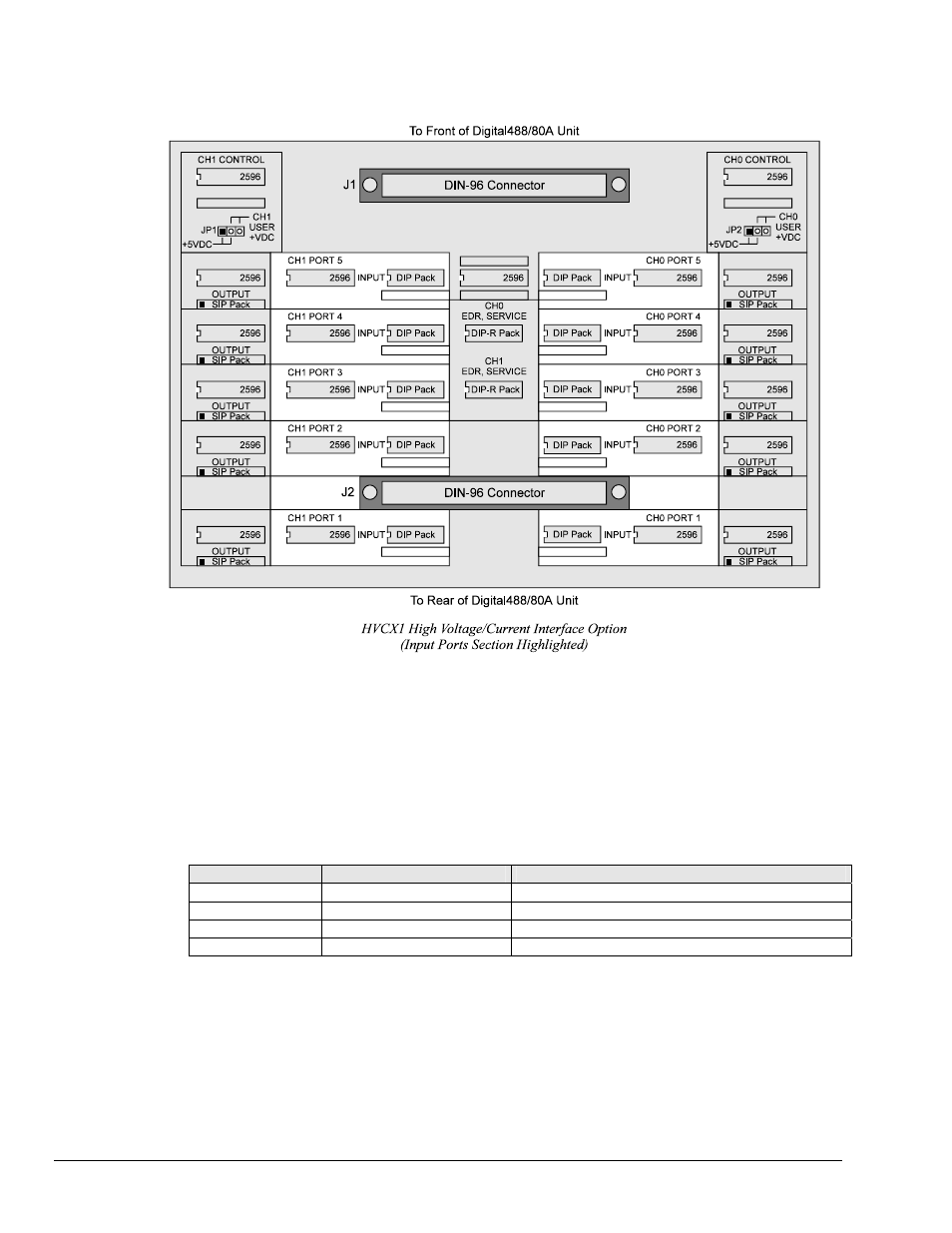
To Set Up Input Ports
Note:
All of the components mentioned below are for the port section of the HVCX1 board
labelled INPUT.
1. Locate the two 5-port sections (one in the right half, one in the left half) of the HVCX1 board labelled
INPUT.
2. Place the 2596 IC chip into the IC input socket of the port being configured. The notched end of the IC
must be to the left (see above figure for the proper orientation).
3. Install the DIP (dual in-line) pack for the voltage desired. See the chart below for the DIP pack
labeling. The notched end of the DIP pack must be to the left (see above figure for the proper
orientation).
Inputs
DIP Resistor Values
Label of DIP Pack Supplied with HVCX1 Option
0-5 V
10 ohms
4116R-001-100
0-12 V
20K ohms
4116R-001-203
0-24 V
56K ohms
4116R-001-563
0-48 V
120K ohms
4116R-001-124
4. Verify that no components (the 2596 and SIP pack) are in the OUTPUT section of a port being
configured as an input. Having components for the output and input installed in the same port will
cause damage to the unit.
12 Digital488/80A Setup
Digital488/80A User's Manual