Hvcx1 option setup…… 10, Hvcx1 option setup caution, Warning – Measurement Computing Digital488/80A User Manual
Page 16
HVCX1 Option Setup
CAUTION
If you would like to experiment with the Digital488/80A unit and the example
programs, do not install the HVCX1 option until after experimenting with the unit to
avoid software/hardware configuration conflicts. If the HVCX1 option is already
installed, replace it with the jumper board to run the example programs.
WARNING
Never disassemble the Digital488/80A case while it is connected to the AC power line!
Internal voltage potentials exist which could cause bodily injury or death!
The HVCX1 High Voltage/Current
Interface option is a configurable daughter
board that allows the Digital488/80A to be
used with solenoids, switching relays and
other high voltage / high current devices.
When using the HVCX1 with an exte
voltage source, the I/O lines may be
configured as high voltage inputs (up to 50
V) or as high voltage / high current ou
The factory default is all 5 V I/O and
handshaking f
rnal
tputs.
or both channels with all ports
r
y be set independently from
set as inputs.
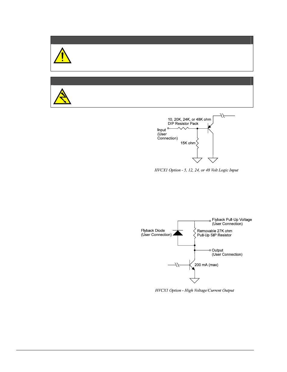
Inputs are configured on a port-by-port
basis (in groups of 8 bits). Inputs can be
configured to be compatible with 5, 12, 24
and 48 volt logic. The interface voltage fo
each port ma
other ports.
t to
),
his
ies protection against inductive
When the HVCX1 option is used, the data
lines of both channels can be configured as
high voltage / high current outputs. Outputs
can support up to 50 VDC at 200 mA no
exceed 8 A total. When the outputs are
configured as high voltage, using internal
pull-up resistors (such as the 27K ohm SIP
all 40 output lines on a channel have their
pull-ups and integral flyback diodes pulled
up to the flyback pin (Pin 48) on the DB-50
connector. When used in this mode, outputs
are configured on a per-channel basis. T
flyback pin should be connected to the
positive supply lead of the power supply
used with the external devices. The flyback
diode suppl
transients.
gh the use of open collector drivers with integral flyback diodes for inductive load transient
For more information, see the "Specifications" section in Chapter 1: Digital488/80A Overview.
Pin 48 sets the pull-up logic level for all output lines on a channel. Lines configured with the pull-up can
only be used as outputs. These outputs can sink up to 200 mA in the ON state and withstand voltages up to
50 VDC throu
suppression.
10 Digital488/80A Setup
Digital488/80A User's Manual