Measurement Computing Digital488/80A User Manual
Page 60
Data received for output to the digital ports must be contained within a
D
command prefix and a
Z
terminator suffix. If
the amount of data sent is less than the number of bits programmed as outputs, then the least-significant bits contain
the data sent and the most-significant bits are cleared to logic 0. If the data sent is greater than the number of bits
programmed for output or selected by the Port Select (
P
) command, then the Digital488/80A generates a Conflict Error
(
E3
) and ignores the entire command string up to the next Execute (
X
) command. The Data Strobe output is pulsed
for approximately 50 microseconds after new data is output on the selected port(s).
When the Digital488/80A is addressed to Talk in Data Ready (
R
) mode
R0
, it asserts Inhibit, reads the data from all 5
ports, unasserts Inhibit, and outputs the number of characters determined by the Bus Input/Output (
G
) and Port Select
(
P
) commands. Leading zeros are not suppressed, and the bus terminators are appended to the output. After output,
the Digital488/80A must be readdressed to Talk to perform subsequent reads. In Data Ready (
R
) mode
R1
or
R2
,
EDR may also be used to capture data in this data format.
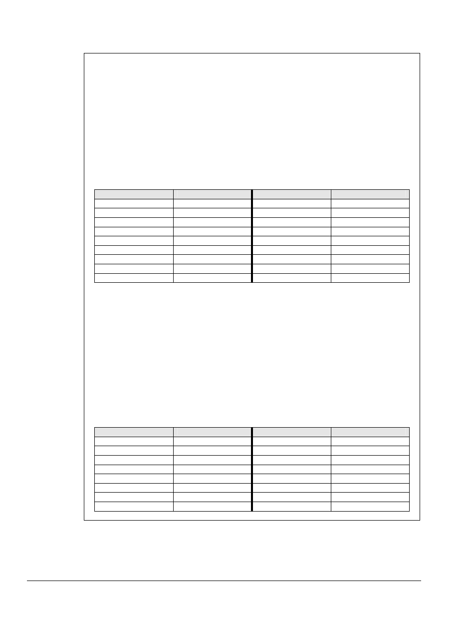
Data Format
F2
- ASCII Binary
In Data Format
F2
, each data bit is described with an ASCII 0 or 1. Each byte is formatted in two 4-bit multiples
separated by semi-colons.
ASCII Binary
Decimal Equivalent
ASCII Binary
Decimal Equivalent
0000;0000
0
0000;1001
9
0000;0001
1
0000;1010
10
0000;0010
2
0000;1011
11
0000;0011
3
0000;1100
12
0000;0100
4
0000;1101
13
0000;0101
5
0000;1110
14
0000;0110
6
0000;1111
15
0000;0111
7
1000;0001
129
0000;1000
8
1111;1111
255
Data received for output to the digital ports must be contained within a
D
command prefix and a
Z
terminator suffix, and
each 4-bit quantity must be separated by semi-colons. Leading zeros are not required. If the amount of data sent is
less than the number of bits programmed as outputs, then the least-significant bits contain the data sent and the most-
significant bits are cleared to logic 0. If the data sent is greater than the number of bits programmed for output or
selected by the Port Select (
P
) command, then the Digital488/80A generates a Conflict Error (
E3
) and ignores the
entire command string up to the next Execute (
X
) command. The Data Strobe output is pulsed for approximately 50
microseconds after new data is output on the selected port(s).
When the Digital488/80A is addressed to Talk in Data Ready (
R
) mode
R0
, it asserts Inhibit, reads the data from all 5
ports, unasserts Inhibit, and outputs the number of characters determined by the Bus Input/Output (
G
) and Port Select
(
P
) commands. Leading zeros are not suppressed, and the bus terminators are appended to the output. After output,
the Digital488/80A must be readdressed to Talk to perform subsequent reads. In Data Ready (
R
) mode
R1
or
R2
,
EDR may also be used to capture data in this data format.
Data Format
F3
- ASCII Decimal
In Data Format
F3
, the data is described in decimal 8-bit multiples and transmitted in ASCII. Each decimal number
(
000
to
255
) to be output must be separated by semi-colons.
ASCII Decimal
Decimal Equivalent
ASCII Decimal
Decimal Equivalent
000
0
008
8
001
1
009
9
002
2
010
10
003
3
020
20
004
4
100
100
005
5
200
200
006
6
210
210
007
7
255
255
54 Digital488/80A Commands
967695
Digital488/80A User's Manual