Te…… 77, Serial poll status byte – Measurement Computing Digital488/80A User Manual
Page 83
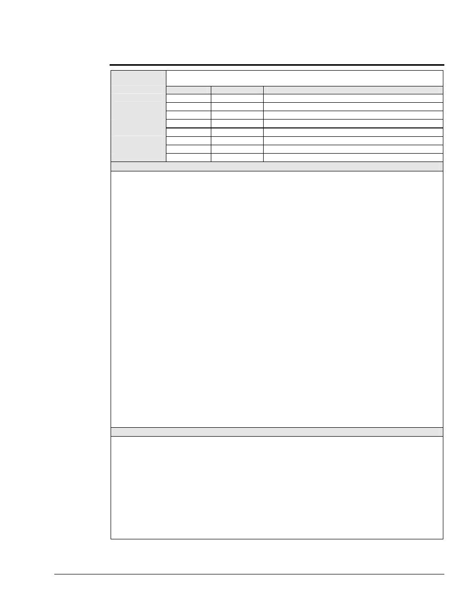
Serial Poll Status Byte
SUMMARY
The Serial Poll Status byte is sent upon receiving the Serial Poll (
SPOLL
) command from the IEEE
488 bus controller.
Bit Location
Decimal Value
Description
DIO1
1
(LSB) Service input transition.
DIO2
2
EDR (External Data Ready) input transition.
DIO3
4
IEEE 488 bus error.
DIO4
8
Not used; always logic 0.
DIO5
16
Ready for more commands.
DIO6
32
Not used; always logic 0.
DIO7
64
Service Request (
SRQ
) bit.
DIO8
128
(MSB) Not used; always logic 0.
DESCRIPTION
The Serial Poll Status byte is sent upon receiving the Serial Poll (
SPOLL
) command from the controller. Refer to the
Service Request Mask (
M
) command description for details on how the Serial Poll Status byte is affected. To enable
each bit to reflect the true status of the device, the appropriate
M
command must be executed. The significance of
each bit in the Serial Poll Status byte is shown below:
•
•
•
•
•
•
•
•
DIO1
: When enabled by the
M1
command, the
DIO1
bit is set by a transition on the Service input line, its active
transition state determined by the Invert (
I
) command
I64
.
DIO1
is cleared after the controller Serial Polls the
Digital488/80A.
DIO2
: When enabled by the
M2
command, the
DIO2
bit is set by a transition on the EDR input line, its active
transition state determined by the Invert (
I
) command
I32
.
DIO2
is cleared after the controller Serial Polls the
Digital488/80A.
DIO3
: The
DIO3
bit is set when an invalid command is sent to the Digital488/80A. The
M4
command enables a
Service Request (
SRQ
) to occur when an invalid command is received. The bit is cleared after the controller
sends the User Status (
U
) command
U0
, and reads the status string from the Digital488/80A.
DIO4
:
DIO4
is not used, and is always a logic 0.
DIO5
: The
DIO5
bit is set after an entire command string has been received and processed by the
Digital488/80A. The bit is cleared while the Digital488/80A is processing commands which have been received
from the controller. When used with the
M16
command, a Service Request (
SRQ
) is also generated when the
DIO5
bit is set. An Execute (
X
) command must be received before the
DIO5
bit can be cleared.
DIO6
:
DIO6
is not used, and is always a logic 0.
DIO7
: The
DIO7
bit is set when the Digital488/80A generates a Service Request (
SRQ
). This is used by the
controller to determine that the Service Request was indeed generated by the Digital488/80A.
DIO8
:
DIO8
is not used, and is always a logic 0.
EXAMPLE
PRINT#1,"CLEAR08"
Line 1: Reset the Digital488/80A.
PRINT#1,"OUTPUT08;M4X"
Line 2: Select
SRQ
on IEEE 488 bus error.
PRINT#1,"OUTPUT08;F7X"
Line 3: Send an invalid bus command. The ERROR and SRQ LED
indicators should light up.
PRINT#1,"SPOLL08"
Line 4: The Serial Poll Status byte returned should be
84
(
64+16+04
). The
interpretation of this Serial Poll Status byte is as follows:
•
64
- The Digital488/80A was the source of the SRQ.
•
16
- The Digital488/80A is ready for more commands.
•
04
- There is an IEEE 488 bus error.
When the Digital488/80A is Serial Polled, the SRQ LED indicator turns off.
Digital488/80A User’s Manual
967695
Digital488/80A Commands 77