F - data format…… 53, F - data format – Measurement Computing Digital488/80A User Manual
Page 59
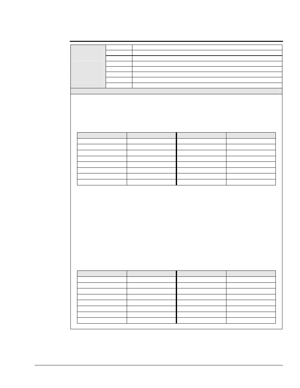
F - Data Format
SYNTAX
Fn
Define format
n
of data, where
n =
value from
0
to
5
.
F0
(Default) Define ASCII hexadecimal (4 bits per character).
F1
Define ASCII character (4 bits per character).
F2
Define ASCII binary (1 bit per character).
F3
Define ASCII decimal (8 bits per number).
F4
Define Binary (each byte = 8 bits).
F5
Define High-speed binary (each byte = 8 bits).
F?
Returns current data format
n
.
DESCRIPTION
The Data Format (
F
) command determines the method by which input and output data are described. The six
available data formats are discussed in the following text.
Data Format
F0
- ASCII Hexadecimal
In the default Data Format
F0
, the data are described in ASCII hexadecimal, with each character having a value from
0
through
9
, or
A
through
F
. Each ASCII character describes 4 bits of data.
ASCII Hexadecimal
Decimal Equivalent
ASCII Hexadecimal
Decimal Equivalent
0
0
8
8
1
1
9
9
2
2
A
10
3
3
B
11
4
4
C
12
5
5
D
13
6
6
E
14
7
7
F
15
Data received for output to the digital ports must be contained within a
D
command prefix and a
Z
terminator suffix. If
the amount of data sent is less than the number of bits programmed as outputs, then the least-significant bits contain
the data sent and the most-significant bits are cleared to logic 0. If the data sent is greater than the number of bits
programmed for output or selected by the Port Select (
P
) command, then the Digital488/80A generates a Conflict Error
(
E3
) and ignores the entire command string up to the next Execute (
X
) command. The Data Strobe output is pulsed
for approximately 50 microseconds after new data is output on the selected port(s).
When the Digital488/80A is addressed to Talk in Data Ready (
R
) mode
R0
, it asserts Inhibit, reads the data from all 5
ports, unasserts Inhibit, and outputs the number of characters determined by the Bus Input/Output (
G
) and Port Select
(
P
) commands. Leading zeros are not suppressed, and the bus terminators are appended to the output. After output,
the Digital488/80A must be readdressed to Talk to perform subsequent reads. In Data Ready (
R
) mode
R1
or
R2
,
EDR may also be used to capture data in this data format.
Data Format
F1
- ASCII Character
In Data Format
F1
, the data are coded and transmitted in ASCII characters with the 4 least-significant bits of each
ASCII character representing 4 bits of data.
ASCII Character
Decimal Equivalent
ASCII Character
Decimal Equivalent
0
0
8
8
1
1
9
9
2
2
:
(colon)
10
3
3
;
(semi-colon)
11
4
4
<
(less than)
12
5
5
=
(equals)
13
6
6
>
(greater than)
14
7
7
?
(question mark)
15
Digital488/80A User’s Manual
967695
Digital488/80A Commands 53