Ining ports setup…… 11 – Measurement Computing Digital488/80A User Manual
Page 17
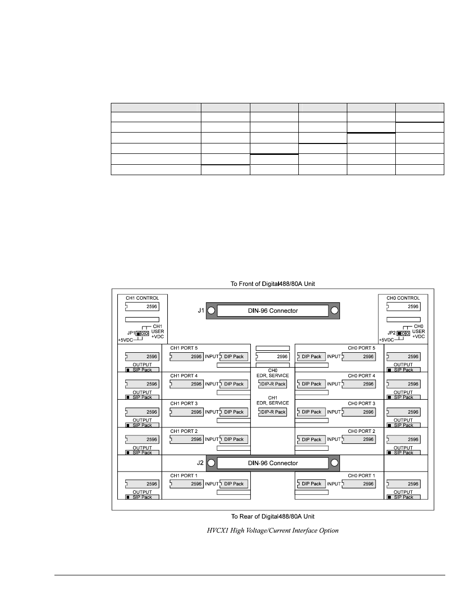
Determining Ports Setup
Before configuring the HVCX1 option, determine which ports are going to be set up for inputs and which
ports for outputs. Determine what voltages are desired for the inputs: 0-5 V, 0-12 V, 0-24 V or 0-48 V.
The following chart shows which combinations of outputs and inputs are permitted (limitations set by the
Configuration (
C
) software command).
Configuration Command
Port 5
Port 4
Port 3
Port 2
Port 1
C0
Input Input Input Input Input
C1
Input Input Input Input Output
C2
Input Input Input Output
Output
C3
Input Input Output Output Output
C4
Input Output Output Output Output
C5
Output Output Output Output Output
Note:
If no chips are installed in the input or output side of a port, the Digital488/80A lines are
pulled up and the user will receive "FF" from that port.
For convenience, you may want to program the Digital488/80A to power up with your configuration.
Refer to the Configuration (
C
) and Save Configuration (
S
) commands. Input or output status is set using
the Configuration (
C
) command. To save the input/output status as the new setting for the power-up
default, it must be saved as part of the Recall Configuration (
O
) command. To set the unit to a particular
configuration upon power on, the Save Configuration (
S
) command must be used once all the desired
options have been selected.
Digital488/80A User’s Manual
11-08-02
Digital488/80A Setup 11