5 – operation – Greenheck AMD-xx-TD Transmitter User Manual
Page 9
9
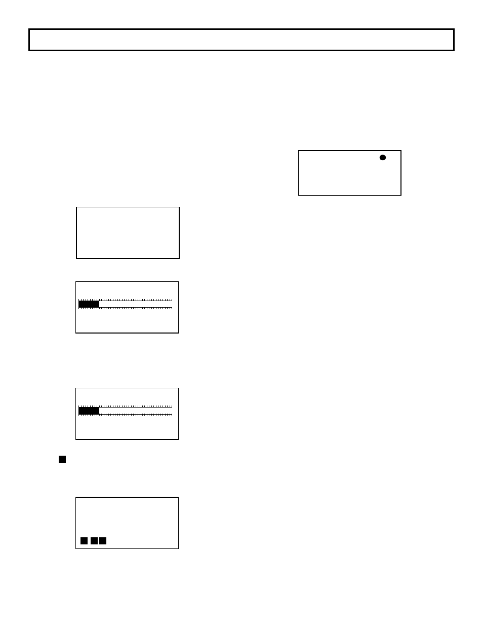
After 20 seconds, the display will return to Normal
display mode, and the dot in the upper right of the
display indicating CPU Activated will blink rapidly (4
times per second). This is Normal operation mode
and no further user interface is required. If, however,
user would like to verify configuration or change user
selectable parameters, continue to Section 5.4 entitled
“CONFIGURATION”.
5 – OPERATION
5.1 – INTRODUCTION
The Vari-Green has been configured at the factory to
customer specified parameters. Review this information
and verify that the Vari-Green set-up is correct for
your application. If any problems or discrepancies are
detected, contact Greenheck Dampers at 1-800-717-
6540 prior to proceeding.
5.2 – START-UP
1. After Installation has been verified in accordance with
Section 4, turn power switch located at the lower front
side to the ON position (see Figure 4.1).
2. Display will briefly indicate:
Followed by:
The number of active sensors will be represented by
the bar graph and listed below. There are 8 active
sensors in this example.
After 5 seconds, display will indicate:
The number of enabled sensors will be represented
by the bar graph and listed below. There are 8 active
sensors in this example.
After 5 seconds, display will indicate:
with the progressing from left to right.
Vari-Green
- - - - - - - - - - - - - - - - - - -
Thanks for Choosing
Greenheck
*
0 ACFM
VELO 0 AFPM
TEMP 68.0°F
1 8 16 24 32
Sensors Found: 8
Total Sensors: 8
1 8 16 24 32
Enabled Sensors: 8
Total Sensors: 8
Vari-Green
®
- - - - - - - - - - - - - - - - - - - -
Sensor Warming Up
Normal
display mode
* Dot flashes 4 times a second, indicating that
CPU is active. If ALERT flashes instead of Dot, see
section for Diagnostics.
5.3 - NORMAL OPERATION
Under Normal operation, the
Vari-Green transmitter will
continuously display flow and velocity, or temperature.
5.4 - CONFIGURATION
The Vari-Green onboard microprocessor controls
Configuration: Operating parameter selection; input/
output activation and scaling, and display scaling.
The customer can verify configuration and change
certain parameters (within defined ranges) by
entering the Vari-Green Configuration mode. This is
accomplished using the four membrane pushbuttons
located on the Vari-Green cover. See Figure 4.1 for
location of pushbuttons.