Greenheck AMD-xx-TD Transmitter User Manual
Page 7
7
4.4 – PROCESS CONNECTIONS
See separate Installation Instructions provided with the Vari-Green Probes or Station for information on connecting
cables from the Probes or Station to the Transmitter.
If the
Vari-Green have been purchased with a factory mounted transmitter, all connector cabling has already been
installed.
4.5 – POWER/SIGNAL CONNECTIONS
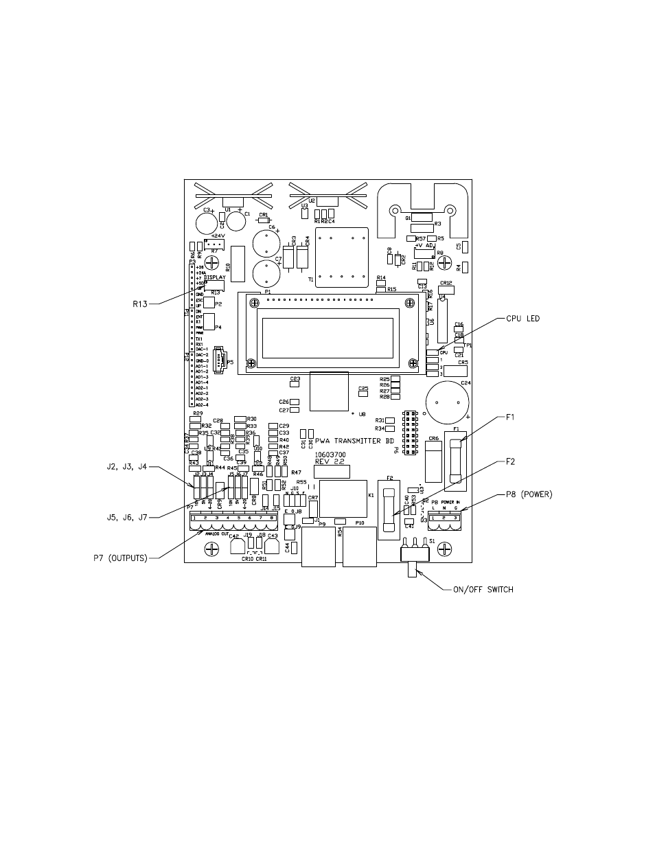
Power wiring is done at terminal strip P8, and signal wiring is done at terminal strip P7. Both P7 and P8 are located
in the lower portion of the transmitter and are accessible by opening the front cover. See Figure 4.2 for location of
P7 and P8. Two conduit openings are provided in the bottom of the transmitter for the power and signal wiring.
OUTPUT #1 (Terminals 1(+) and 2(-), P7).
This output represents the measured airflow and is
sourced (powered) by the Vari-Green. Output can be
configured for 0-5VDC, 0-10VDC, or 4-20mADC. Review
Factory Set-Up Information Sheet for your configuration.
If output is to be 0-5VDC:
Position both jumpers on
J3. See Figure 4.2.
If output is to be 0-10VDC: Position both jumpers on
J2. See Figure 4.2.
If output is to be 4-20mADC: Position both jumpers on
J4. See Figure 4.2.
In addition to positioning the jumpers for the desired
output type, the corresponding output type must be
selected in the Operator Menu (see Section 5.12).
Figure 4.2
WIRING.
It is recommended that power wiring be 14 awg to 18
awg, and signal wiring should be 14 awg to 22 awg.
14 awg is the maximum wire gauge that the terminals
can accommodate. No more than two wires should be
connected to any one terminal. To aid in the wiring of
both power and signal wires, P7 and P8 are removable
by pulling the terminal strip straight up and off the circuit
board. Once wiring has been completed, replace the
terminal strip by aligning with receptacle and pressing
firmly.
POWER 24 VAC/DC (Terminals L, N and G, P8).
Power required by the Vari-Green must be connected
to the two terminals labeled L(+) and N(–). Earth ground
must be connected to the terminal labeled G.
Power
Supply must be 20-28VAC or 20-40VDC.