4 – diagnostic display selection, 5 – diagnostic alert determination – Greenheck AMD-xx-TD Transmitter User Manual
Page 29
29
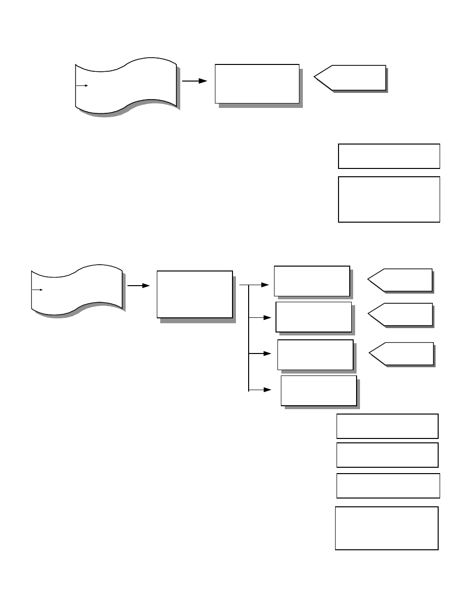
6.4 – Diagnostic Display Selection
Diagnostic Display
Sensor Number: 1
VELO XXX SFPM
TEMP XX.X°F
1 to 32
1
- Sensor Management
Diagnostic Display Selection
- Diagnostic ALERT Determin
Supervisor Menu
Diagnostic Display
Available selections:
Velocity & temperature units depend
on selections made in Flow
Configuration in Operator Menu.
1
Depends on # of
sensors installed.
1. While in Main menu, use UP and DN to scroll:
2. Press ENT. Display will indicate:
3. Use UP and DN to scroll through all enabled sensors.
4. When done, press ESC and siplay will return to previous menu (see Step 1).
Diagnostic Display
Selection
Diagnostic Display
Sensor Number: 1
VELO
XXX SFPM
TEMP
XX.X°F
6.5 – Diagnostic Alert Determination
- ALERT for Sensors
- ALERT for Averages
- Turn Off/On ALERT
for Missing Sensors
- Return to MAIN MENU
ALERT for Sensors
NO ALERT EXISTS
Return to
MAIN MENU
ALERT for Averages
NO ALERT EXISTS
Turn Off/On
ALERT ON
See table below for
Sensor ALERT
code & definition
See table below for
Averages ALERT
code & definition
ON or OFF
- Diagnostic Display Selection
Display ALERT Determination
- Power Cycle Sensor Network
Supervisor Menu
Diagnostic ALERT Menu
1. While in Main Menu, use UP or DN to scroll to:
2. Press ENT. Display will indicate:
3. Press ENT. Display will indicate:
or if an ALERT does exist, display will indicate:
Definitions of individual sensor ALERT codes are found at the end of this Section.
Diagnostic ALERT
Determination
ALERT for Sensors
ALERT for Sensors
NO ALERT EXISTS
Sensor Number: 1
ALERT CODE: 1
Sensor has not
responded