13 – transmitter output calibration – Greenheck AMD-xx-TD Transmitter User Manual
Page 18
18
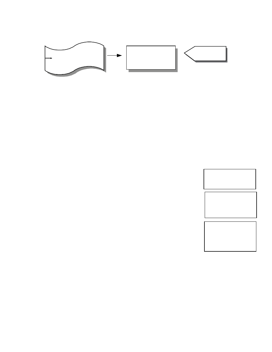
5.13 – Transmitter Output Calibration
Allows for the calibration of the Vari-Green analog outputs.
Note: Unit is supplied Factory calibrated.
This section can be accomplished with the Vari-Green mounted in its operating location or at a test bench in a calibration
lab.
Required Equipment.
1. Digital Multimeter
Preparation.
1. Turn Power switch OFF on the Vari-Green (see Figure 4.1).
2. Open cover of the Vari-Green.
3. Remove all wires connected to terminals 1 through 4 (see Figure 4.2).
4. Turn Power switch ON.
1. While in Operator Menu, use UP or DN to scroll to:
2. Press ENT to enter Display Configuration menu. Display will indicate:
3. Press ENT. Display will indicate:
4. Connect a DMM set for type and scale of Transmitter Output 1 (as indicated on display)
across terminals 1 and 2 on the Vari-Green (see Figure 4.2).
Note: If the output is 4-20mA, a load resistance should be in series with the DMM. This can be accomplished by
connecting the actual process load or a resistor of similar value to the actual process load.
DMM should be reading a minimum value; 0.00 ± 0.01 volts or 4.00 ± 0.01mA.
5. If DMM is reading out of tolerance, use UP or DN to adjust the Vari-Green output for an acceptable DMM reading.
Depending on DMM’s selected range, the UP or DN button may need to be pressed and held for a period of time
before any change occurs in the DMM’s display. To speed up changes in output, pushbutton combinations can be
used. The following chart lists these combinations along with the associated change in output type.
Transmitter Output
Calibration
Output 1 Zero
Selection
Type is 4-20 mA
Output 1 Zero
Perform Calibration
Type is 4-20 mA
- Output 1 Zero Selection
- Output 1 Span Selection
- Output 2 Zero Selection
- Output 2 Span Selection
- Return to MAIN MENU
See Calibration
Instructions
- Output Signal type Selection
Transmitter Output Calib.
- K-Factor Configuration
Operator Menu
Output Calibration Menu