Gasboy Fuel Point Dispenser User Manual
Page 27
Vapor Recovery Retrofit Kits
03/28/03
4-3
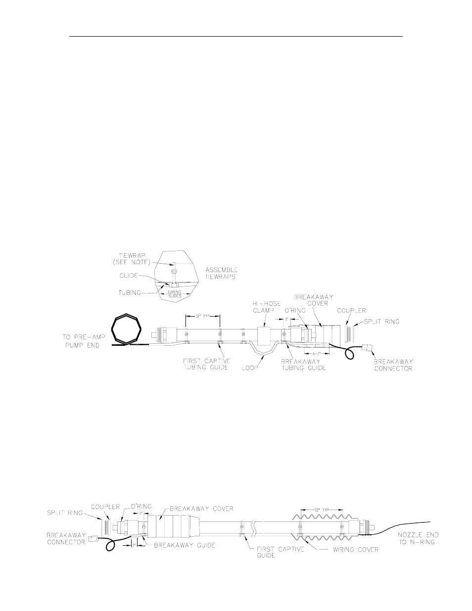
STEP A: CONSTRUCT VAPOR RECOVERY HOSE ASSEMBLIES
Hose 1 Assembly (Pump End)
1. Balanced hose assemblies require removal of one threaded coupler before proceeding.
Starting at the breakaway end, remove split ring and carefully remove coupler. Be careful not
to damage the O-ring seals. Set aside coupler and split ring for re-installation during Step C:
Final Vapor Recovery. (For high hose retractor applications, add the high hose clamp
approximately 6” from the hose end.)
2.
Add PVC wire covers, trimming as needed with sharp scissors. Do not over-trim openings,
covers should fit tightly around hose.
3.
Locate the appropriate wire assembly from the kit and assemble to the hose with 8” tiewraps
approximately at 12” centers (See diagram below). Slide tiewraps between the tubing and
the guide. Tiewraps must be assembled to allow the wire assembly to slide through the
plastic guides. (See diagram below). Do not tighten fully to allow adjustment during Final
Assembly. Inspect and lubricate O-ring and reassemble coupler to hose end. When a
clamp is used, adjust tubing to form a 2-3” loop.
Hose 2 Assembly (Nozzle End)
4. Assemble the nozzle end hose repeating Steps 1-3. Hose wire tubing is furnished to fit
popular hose lengths. The small parts kit contains parts to lengthen the tubing two
additional feet. For additional lengths less than two feet, the tubing can be cut to desired
length using a hacksaw and then deburred using a small file. To assemble the added
tubing, start at the nozzle end (end without connector) and cut the tiewrap. Assemble
bushings and tubing, compress slightly and hold in place using the small tiewrap supplied
with the kit.