Gasboy Fuel Point Dispenser User Manual
Page 28
GASBOY Fuel Point System
4-4
03/28/03
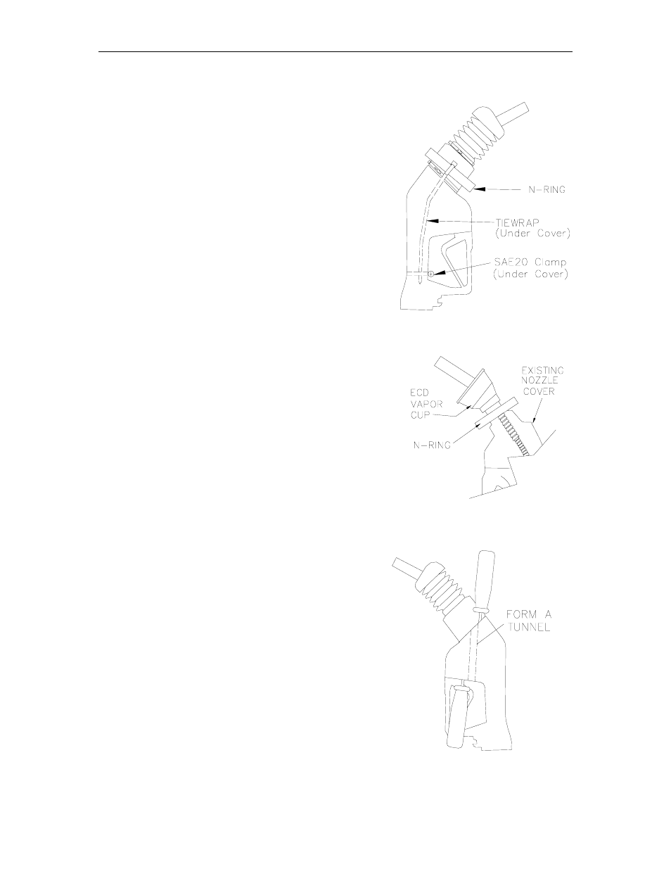
STEP B: NOZZLE ASSEMBLY
1. See Vapor Recovery Nozzle list (Section 2) for
nozzles approved by UL for use with Fuel Point.
Locate the N-Ring assembly and follow Step 2 for
balanced nozzle assemblies or follow Step 3 for Vapor
Assist nozzles.
2. For balanced nozzles with bellows, measure the
diameter of the bellows at the base of the spout just
above the check valve, if present. Trim the N-ring
membrane to a diameter slightly smaller than the
measured diameter. Pull the N-ring assembly over
the bellows end cap and position it at the bellows
base.
3. For assist-style nozzles using an ECD cup:
Increase the size of the opening in the N-ring
membrane enough to slip over the ECD cup.
Position the N-ring at the base of the nozzle spout.
4. Carefully feed the N-Ring cable under the nozzle
cover and along one side of the nozzle (See TIP
below). On the opposite side of the N-Ring, install
an 11” tiewrap and feed the tail under the cover and
down the opposite side of the nozzle.
TIP:
Using two large screwdrivers, insert one from
the fuel spout end and the second from the
opposite end forming a tunnel to feed the
cable and the tiewrap under the nozzle cover.
Lift handles to enlarge the tunnel.
5.
Assemble an SAE 20 mini-clamp around the nozzle
handle under the PVC cover to hold the cable and
tiewrap in place (see diagram above right). Adjust
the tubing and clamp so the does not interfere with
the nozzle handle operation. Set assembled nozzle
aside for final assembly later.