1 in the kit, locate the parts shown in figure 11 – Gasboy M06245K0XX User Manual
Page 20
Installing the Pulser Kit in Single Unit and 9140 (Kits M06245K004 through M06245K007 and M06245K009 - M06245K011)
Page 20
MDE-4506A Atlas™ Pulser Kits M06245K0XX Installation · May 2006
Completing Assembly and Mounting Pulser Unit on Model 9140 (Kits
M06245K009, M06245K010 and M06245K011)
1
In the kit, locate the parts shown in
2
Feed the pulser and coupling assembly wires through the 025015 elbow and install the elbow
on the pulser and coupling assembly.
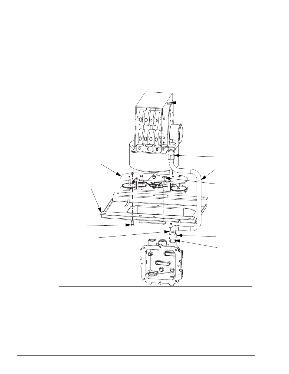
Figure 11: Super-Hi Mechanical Pulser Conduit and Computer Mount
Ref: Plate Assembly,
Computer Mount
Ref: Screw Metric
M6x 16
Bushing, Reducing
3/4-1/2 (K43850)
Conduit, Pulser
Mechanical Super-HI
(M06869B001)
Ref: Screw self
locking hex head cap
3/8 -24x0.75
grade 5
Elbow, Conduit 1/2x
45 deg (025015)
Union, conduit 1/2
inch (Q10016-04)
Ref: Differential Assembly
Elbow, 1/2 x 90MxF
(K42448)
Spacer 0.944
(056877, 056895)
Spacer (056895)
3
Install the M06869B001 conduit on the pulser and coupling assembly (to the elbow installed
in the previous step).
4
Remove and discard the two assembly screws and replace them with the two spacers in the
position shown in
. Notice the difference in part numbers and the position of the
spacers.