Connecting the wires in the junction box – Gasboy M06245K0XX User Manual
Page 13
MDE-4506A Atlas™ Pulser Kits M06245K0XX Installation · May 2006
Page 13
Installing the Pulser Kit in Twin Units (Kits M06245K001 through M06245K003 and M06245K008)
For Kit M06245K008, refer to
.
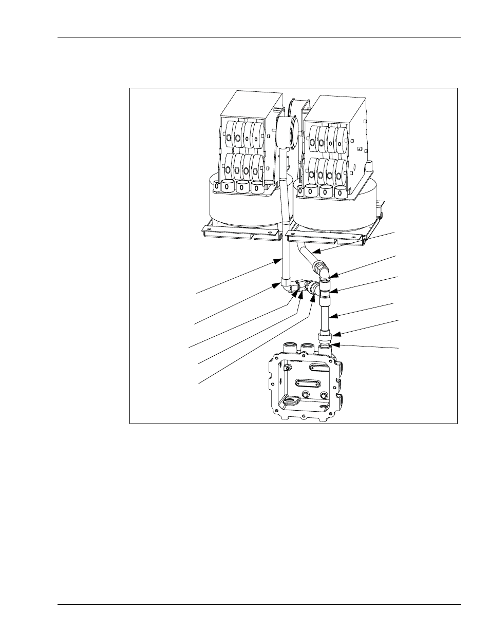
Figure 6: Dual Money Mechanical Pulser Conduit
Bushing, Reducing
3/4-1/2 (K49827)
Conduit Nipple 1/2x 4
(R11976-57)
Conduit Tee 1/2
inch NPT (064830)
Elbow, Conduit 1/2x
90 deg (025045)
Union, conduit 1/2
inch (Q10016-04)
Formed conduit
Mechanical Money
pulser grade 1
(M05368B001)
Conduit elbow 1/2
NPT 90 deg (K42428)
Conduit Nipple
1/2x 1 5/8 (R11976-43)
Elbow, Conduit 1/2x
90 deg (025045)
Union, conduit 1/2
inch (Q10016-04)
Formed conduit
Mechanical Money
pulser grade 2
(M05369B001)
3
Install the K49827 reducer and Q10016-04 union into the junction box as shown in
4
Make the remaining connections as shown in
Connecting the Wires in the Junction Box
1
Remove the screws securing the cover on the junction box. Save screws for remounting.
2
Inside the junction box, connect the two green ground leads from the pulsers to a secure
known ground.
3
Connect the leads for the pulsers, two from the front pulser with black band (mounted to the
left computer) and two from the back pulser (mounted on the right computer) to the leads in
the junction box marked for the pulsers.
4
Remount the junction box cover and secure with the screws removed in