1 in the kit, locate the following parts – Gasboy M06245K0XX User Manual
Page 10
Installing the Pulser Kit in Twin Units (Kits M06245K001 through M06245K003 and M06245K008)
Page 10
MDE-4506A Atlas™ Pulser Kits M06245K0XX Installation · May 2006
Completing the Assembly and Mounting the Pulser Units
1
In the kit, locate the following parts:
• Two 0469XX* pulser and coupling assemblies
• Two 056895 spacers
• Two 056877 spacers
• Four Q10624-37 screws
• Four 068891 washers
• Two 025015 elbows
• One M05293B001 formed conduit (Kits M06245K001, M06245K002, and M06245K003)
• One M05292B001 formed conduit (Kits M06245K001, M06245K002, and M06245K003)
• One M05368B001 formed conduit (Kit M06245K008)
• One M05369B001 formed conduit (Kit M06245K008)
* The part number depends on which kit is being installed. See
the part number.
2
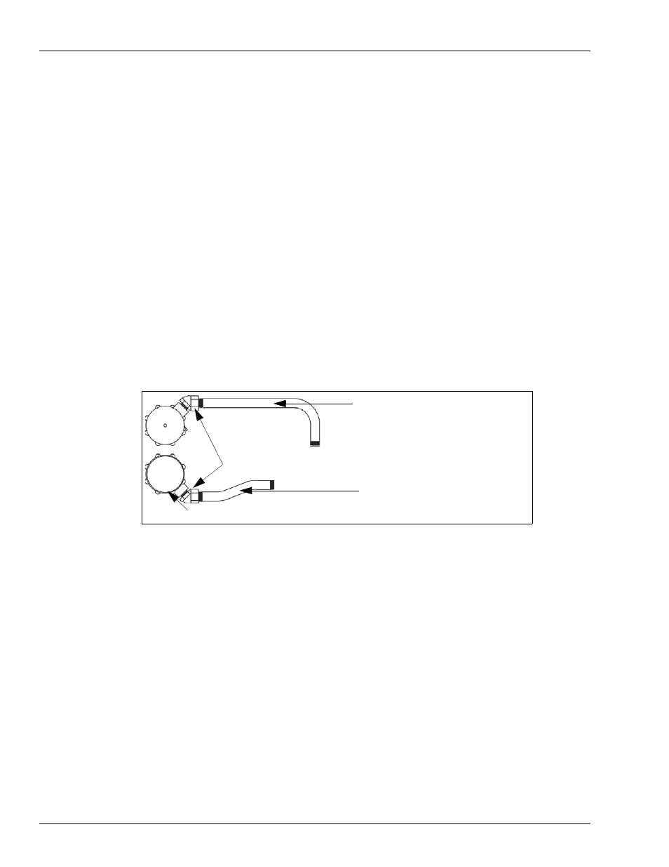
Feed the pulser and coupling assembly wires through the 025015 elbow and install the elbow
on the pulser and coupling assembly. See
Figure 3: Pulser and Coupling Assembly
025015 elbows
M05293B001 conduit (Kits M06245K001,
M06245K002, and M06245K003)
M05369B001 conduit (Kit M06245K008)
M05292B001 conduit (Kits M06245K001,
M06245K002, and M06245K003)
M05368B001 conduit (Kit M06245K008)
Front pulser facing J Box
3
for the second pulser and coupling assembly.
4
Install the M05292B001 or M05368B001 conduit on the front pulser and coupling assembly
(the one with the black band near the end of the wires) and the M05293B001 or M05369B001
on the back pulser and coupling assembly.
Note: The front of the dispenser is the side with the junction box. The front pulser (mounts on
the left computer) is the one with the black band near the end of the wires.