Installing the plate and idler assembly, 2 tighten all screws equally, Caution – Gasboy M06245K0XX User Manual
Page 16
Installing the Pulser Kit in Single Unit and 9140 (Kits M06245K004 through M06245K007 and M06245K009 - M06245K011)
Page 16
MDE-4506A Atlas™ Pulser Kits M06245K0XX Installation · May 2006
Installing the Plate and Idler Assembly
1
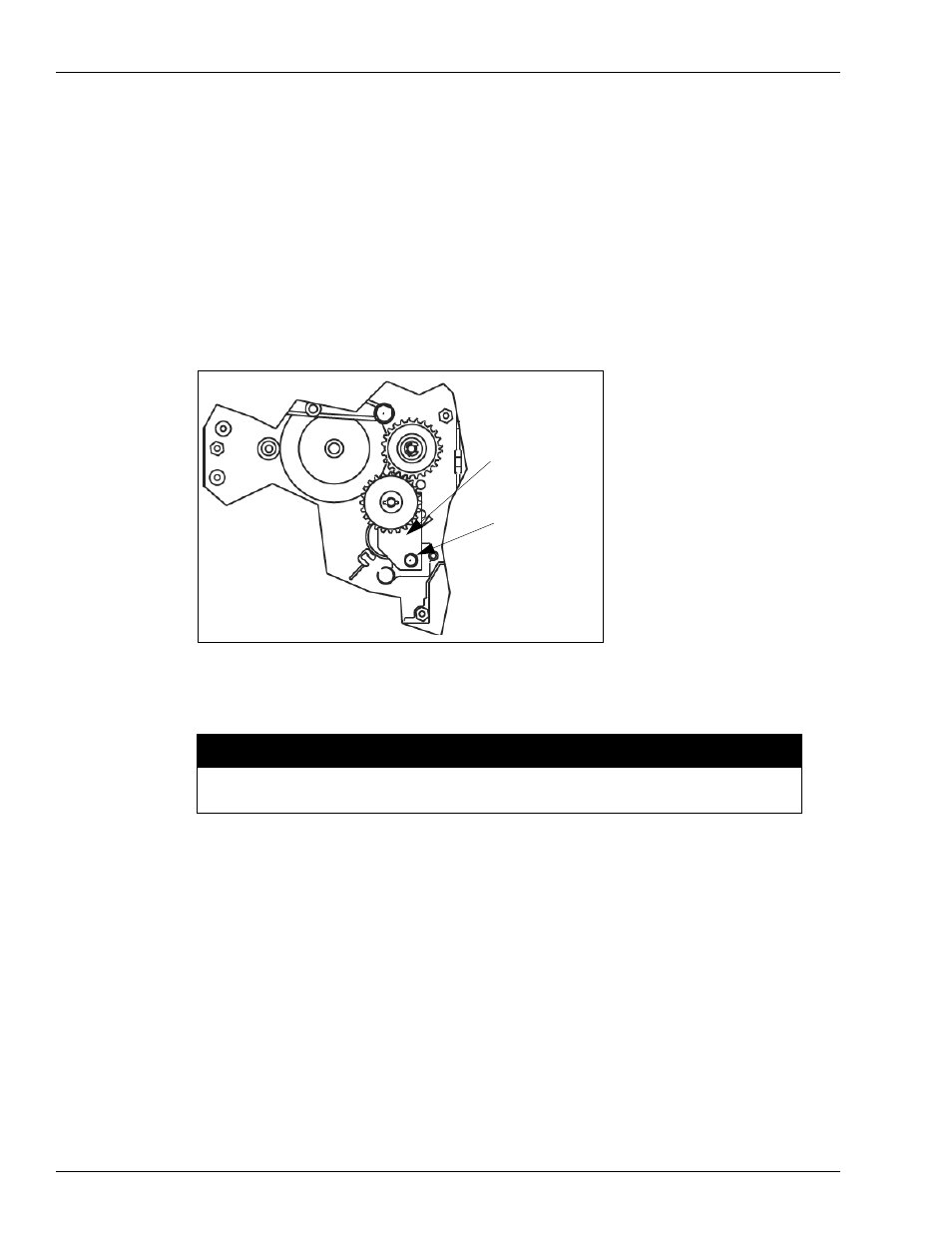
In the kit, locate the K85736-39 screw and the 027044 Plate and Idler Assembly. See
.
Note: The K85736-39 mounting screw for the Plate and Idler Assembly is a self-tapping
screw. Turning the screw into the mounting hole in the computer side frame and then
removing it without the assembly in place will make mounting the assembly easier.
2
Hold the Plate and Idler Gear Assembly in place and loosely secure with the mounting screw.
The boss and bracket holes in the computer assembly must align for proper gear meshing.
Figure 8: Plate and Idler Gear Assembly
Mounting
Screw
Plate and Idler
Gear Assembly
Note: This illustration is shown rotated 90 degrees from its installed position.
Excessive tightening of the mounting screw will crack the plastic plate
.
CAUTION
3
Ensure proper gear position, alignment and meshing and then tighten the mounting screw.
Assembling 046970 Pulser Mounting Plate and 0469XX Pulser and
Coupling Assembly
In the kit, locate a 046970 mounting plate, a 0469XX* Pulser and Coupling Assembly, three
K14830 screws, and three 068891 lock washers.
* The part number depends on which kit is being installed. See
for the
part number.
1
Place the mounting plate on the Pulser and Coupling Assembly, align the three mounting
holes, and loosely secure with three screws and three lock washers.
2
Tighten all screws equally.