Led indicators, About serial port cabling, Serial port pinouts – Digi CM User Manual
Page 143
Hardware Information
Chapter 17
143
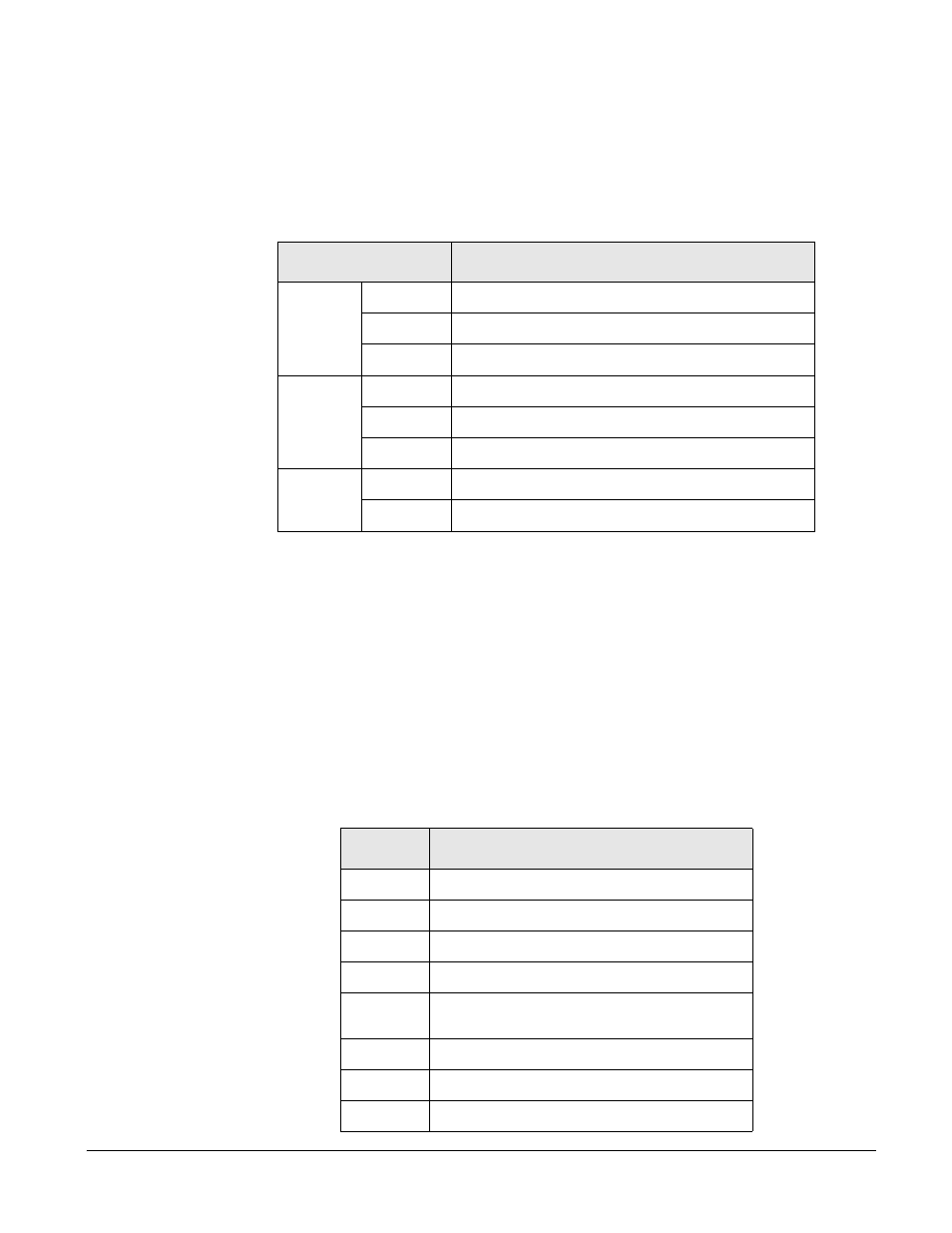
LED Indicators
Use the LED indicators to confirm your attachment to the network and that the
Digi CM is able to send and receive data.
*Not available on the Digi CM 48
About Serial Port Cabling
The Digi CM simplifies cabling. The RJ-45 8-pin configuration matches all
SUN and Cisco RJ-45 console port configurations, enabling CAT 5 cabling
without pinout concerns. Three DB-25 and one DB-9 adapters come in the
package. A DB-25 male, a DB-25 female, and a DB-9 adapter support console
management applications. A DB-25 male adapter provides a modem
connection. See the cable adapter information that follows later in this chapter.
Note:
The cable length restrictions common to RS-232 cables apply to the Digi CM
serial cable as well.
Serial Port Pinouts
The Digi CM uses an RJ-45 connector for serial ports. Pin assignments are
listed in the following table.
LED
Function
System
Power
On when power is supplied
Ready
On when system is ready to run
PC
On when a PC device is running
Ethernet
100Mbps
On when 100Base-TX connection is detected
LINK
On when connected to an Ethernet network
Act
Blinks when there is activity on the Ethernet port
Serial
port*
In use
On when the serial port is ready to run
Rx/Tx
Blinks when there is traffic on the serial port
Pin
Description
1
CTS
2
DSR
3
RxD
4
GND
5
DCD Note: Inbound signal can also be
used as a second ground.
6
TxD
7
DTR
8
RTS