2 front panel led indicators, 3 front panel keypad – Comtech EF Data DMD2401/DMD2401L User Manual
Page 41
User Interfaces
DMD2401/DMD2401L/DMD2401 IBS/IDR Satellite Modem
4-2
TM065 – Rev. 3.3
4.1.2 Front Panel LED Indicators
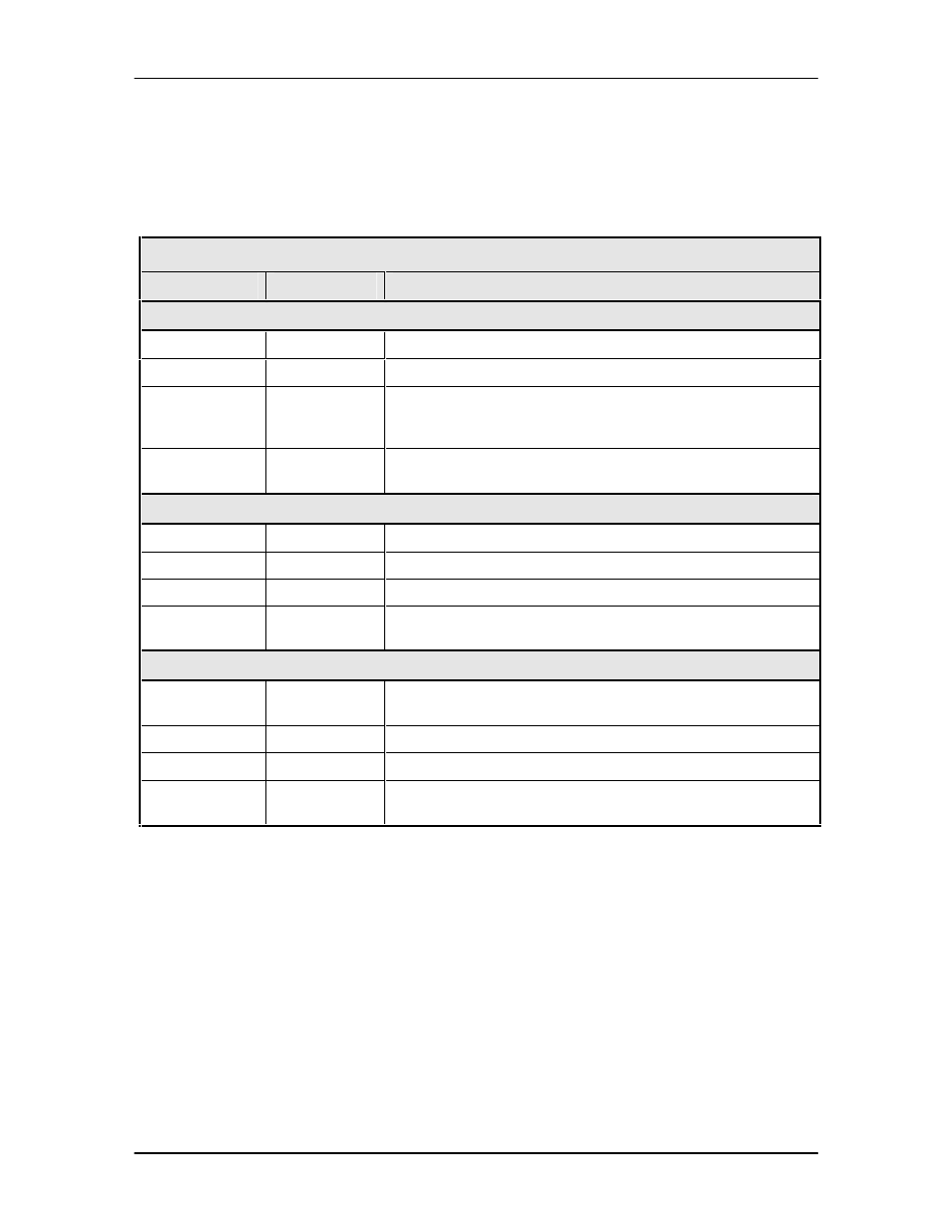
Eight LEDs on the DMD2401 front panel (Refer to Table 4-2) indicate the status of the
DMD2401’s operation. The LED colors maintain a consistent meaning. Green signifies that the
indication is appropriate for normal operation, Yellow means that there is a condition not proper
for normal operation, and Red indicates a fault condition that will result in lost communications.
Table 4-2.
LED
Color
Function
Modem LED Indicators
Power
Green
Indicates that the unit is turned on.
Fault
Red
Indicates a hardware fault for the unit.
Event
Yellow
Indicates that a condition or event has occurred that the
modem has stored in memory. The events may be viewed
from the Front Panel or in the Terminal Mode.
Remote
Green
Indicates that the unit is set to respond to the remote control
input.
Modulator LED Indicators
Transmit On
Green
Indicates that the Transmit Output is currently active.
Major Alarm
Red
Indicates that the Transmit Direction has failed, losing traffic.
Minor Alarm
Yellow
Indicates that a warning condition exists.
Test Mode
Yellow
Indicates that the modulator is involved in a current Test
Mode activity.
Demodulator LED Indicators
Signal Lock
Green
Indicates that the receiver locked to an incoming signal,
including FEC Sync.
Major Alarm
Red
Indicates that the Receive Direction has failed, losing traffic.
Minor Alarm
Yellow
Indicates that a Receive Warning Condition exists.
Test Mode
Yellow
Indicates that the receiver is involved in a current Test Mode
activity.
4.1.3 Front Panel Keypad
The front panel keypad consists of two areas: a 10-key numeric entry with 2 additional keys for
the ‘Enter’ and ‘Clear’ function. The second area is a set of ‘Arrow’ or ‘Cursor’ keys (
n
), (
p
), (
o
),
(
m
), used to navigate the parameter currently being monitored or controlled. Table 4-3 describes
the key functions available at the front panel.