Comtech EF Data DMD2401/DMD2401L User Manual
Page 164
DMD2401/DMD2401L/DMD2401 IBS/IDR Satellite Modem
Electrical Interfaces
TM065 - Rev. 3.3
5-25
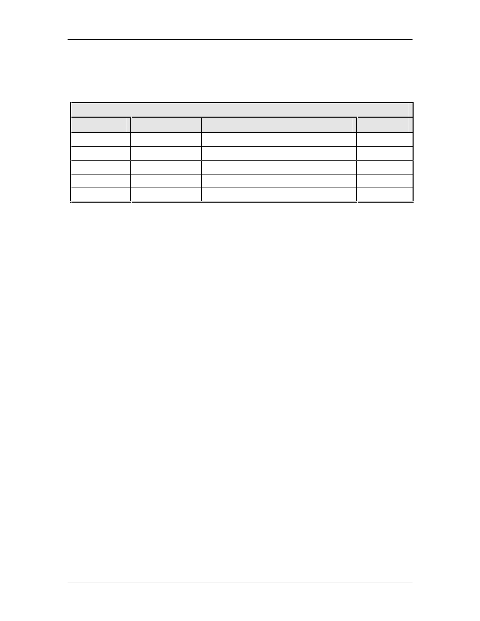
5.7.7 REMOTE (J7)
The Remote Port (J7) is the RS-485 connection for remote monitor and control of the modem. It
is a 9-Pin Female “D” Connector. Refer to Table 5-23 below for the connector pinouts.
Table 5-23. RS-485 Remote Port – 9-Pin Female “D” Connector (J7)
Pin Number
Signal
Description
Direction
1
RS-485 TxD-B
Transmit Data B
Input
5
GND
Ground
–
6
RS-485 TxD-A
Transmit Data A
Output
8
RS-485 RxD-B
Receive Data B
Input
9
RS-485 RxD-A
Receive Data A
Input
5.7.8 SWITCH INTERFACE (J8)
The Switch Interface Port (J8) is the redundancy switch connector. It is a 68-Pin High-Density
Female Connector. Refer to Table 5-8 for connector pinouts.
5.7.9 SD (J9)
The Send Data Port (J9) is the unbalanced Send Data BNC Connector.
5.7.10 G.703 BAL (J10)
The G.703 Balanced Port (J10) is a 15-Pin Female “D” Connector. Refer to Table 5-14 for
connector pinouts.
5.7.11 RD (J12)
The Receive Data Port (J12) is the unbalanced Receive Data BNC Connector.
5.7.12 ESC ALARMS (J14)
The ESC Alarm Interface Port (J14) is a 25-Pin Female “D” Connector. Refer to Table 5-12 for
connector pinouts.
5.7.13 ESC 8K DATA (J15)
The ESC 8K Data Port (J15) is a 15-Pin Female “D” Connector. Refer to Table 5-13 for
connector pinouts.
5.7.14 ESC 64K DATA/AUDIO (J17)
The ESC 64 K Data/Audio Port (J17) is a 9-Pin Female “D” Connector. Refer to Tables 5-15 and
5-16 for connector pinouts.