Comtech EF Data DMD2401/DMD2401L User Manual
Page 165
Electrical Interfaces
DMD2401/DMD2401L/DMD2401 IBS/IDR Satellite Modem
5-26
TM065 – Rev. 3.3
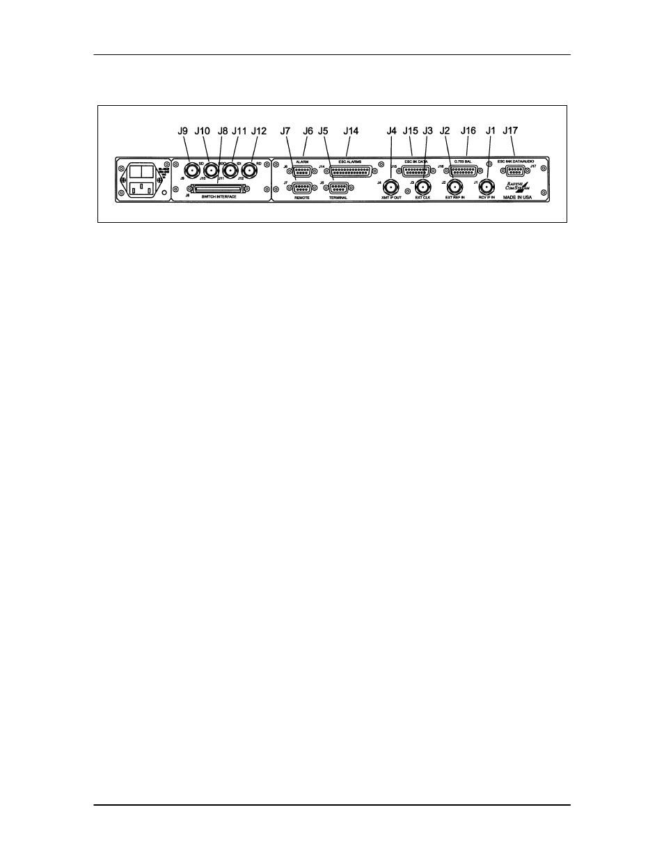
5.8 DMD2401 Universal Interface
Figure 5-6. DMD2401 Satellite Modem Universal Interface Connectors
5.8.1 RCV IF IN (J1)
The Receive IF Input (J1) is the 50 – 90 MHz, and 100 – 180 MHz Demodulator IF Input.
5.8.2 EXT REF IN (J2)
The External Reference Input Port (J2) is used for injecting an external reference frequency into
the modem. The DMD2401 Master Oscillator is locked to this source. All internally generated
frequencies within the modem will attain the stability of the applied external reference. The
external reference must meet the following parameters:
Frequency:
10 MHz, 9 MHz, 5 MHz, 2.048 MHz or 1.024 MHz.
Amplitude:
0.2 Vp-p to 5 Vp-p
Type:
Sinewave or Squarewave
5.8.3 EXT CLK (J3)
The External Clock Port (J3) is used for injecting an external data clock into the modem. The
data symbol clocks may then be selected to be locked to this source. The external clock must
meet the following requirements:
Frequency:
9600 Hz to 2.048 MHz
Amplitude:
0.2 Vp-p to 5 Vp-p
Type:
Sinewave or Squarewave
5.8.4 XMIT IF OUT (J4)
The Transmit IF Output Port (J4) is the 50 – 90 MHz, and 100 – 180 MHz Modulator IF Output.
5.8.5 TERMINAL (J5)
The Terminal Port (J5) pinouts are listed in Table 5-2.