Comtech EF Data DMD2401/DMD2401L User Manual
Page 120
DMD2401/DMD2401L/DMD2401 IBS/IDR Satellite Modem
User Interfaces
TM065 - Rev. 3.3
4-81
Bit 2 = Spare
Bit 3 = IBS BER Alarm
Bit 3 = IBS Prompt Alarm
Bit 5 = IBS Service Alarm
Bits 6 -7 = Spares
(0 = Pass, 1 = Fail)
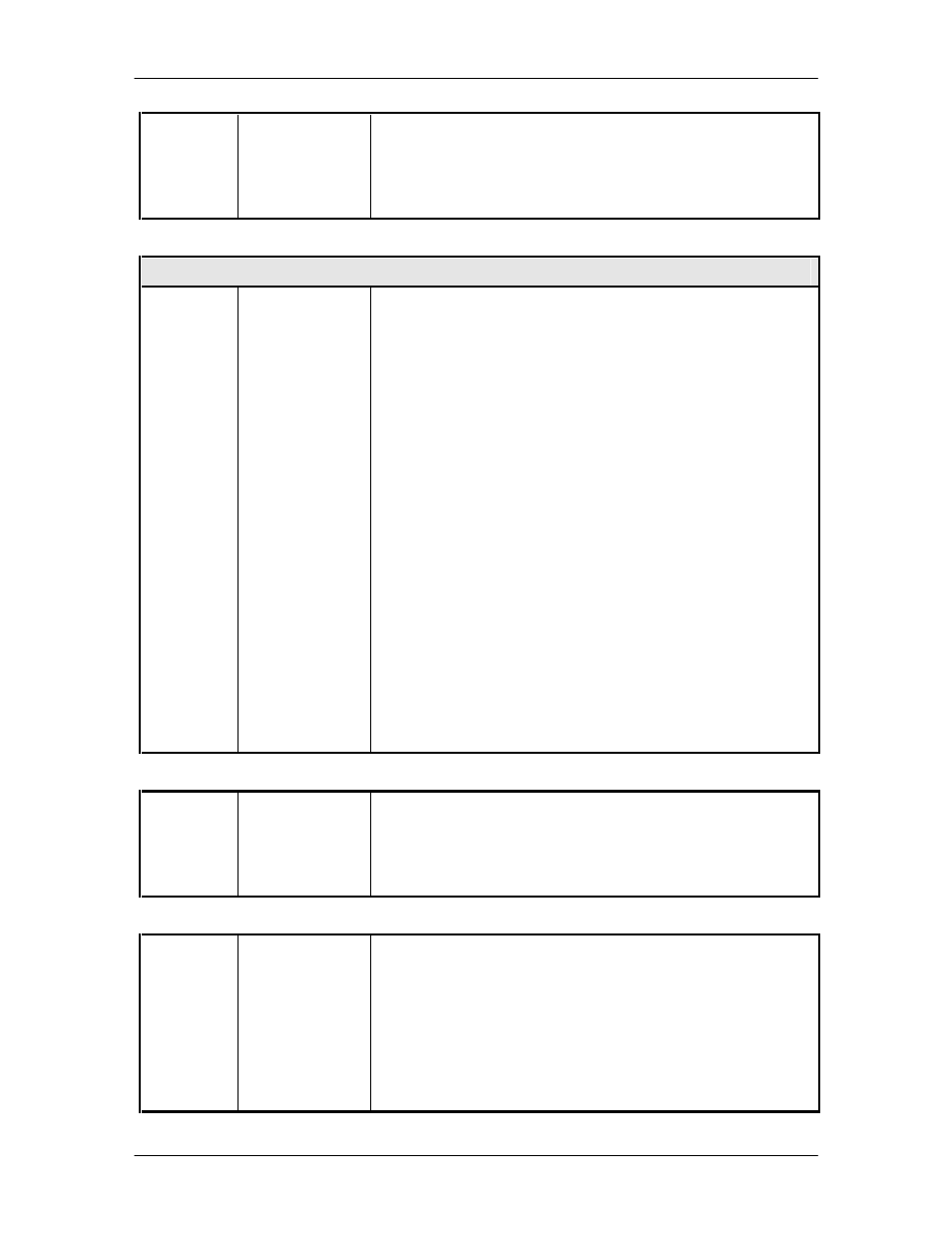
Opcode: <240Dh>
Query a Demodulator’s Eb/No, BER, Level, and AGC Voltage
Query response
<2>
<2>
<2>
<1>
<1>
<1>
<1>
<1>
<1>
Raw BER
Mantissa
Corrected BER
Mantissa
EbNo
Raw BER
Exponent
Corrected BER
Exponent
BER/EbNo Status
Input Level
Input Level
State
AGC Voltage
Bytes 1 - 2 = Unsigned Binary Value Raw BER
Bytes 1 - 2 = Unsigned Binary Value Corrected BER
Unsigned Binary Value, 2 Decimal Places Implied
Byte 3 = Unsigned Binary Value Exponent
Byte 3 = Unsigned Binary Value Exponent
Bit 0 = Raw BER and Corrected BER Status (1 = Valid)
Bit 1 = Test 2047 BER Status (1 = Valid)
Bits 2 - 3 = EbNo Status (0 = EbNo is Invalid, 1 = EbNo is
Valid, 2 = EbNo is Smaller Than Indicated Value, 3 =
EbNo is Greater Than Indicated Value)
Bits 4 - 7 = Reserved
Binary Value in -1 dB Steps, Negative Sign Implied
Signed Binary (0 = Equal to, 1 = Greater Than, -1 = Less Than
Value in -1 dB Steps, Negative Sign Implied
In Hex, decimal point implied.
Opcode: <2437h>
Query a Demodulator’s Lock Status
<1>
Lock Status
Bit 0 = Demod Chipset Lock (0 = Unlocked, 1 = Locked)
Bit 1 = Viterbi Lock (0 = Unlocked, 1 = Locked)
Bit 2 = Reed-Solomon Lock (0 = Unlocked, 1 = Locked)
Bit 3 = Sequential Lock (0 = Unlocked, 1 = Locked)
Bits 4 – 7 = Spares
(Decoders not in use default to locked state)
Opcode: <2A00h>
Command a Demodulator’s Configuration
<4>
<4>
<1>
<4>
<1>
Frequency
Data Rate
Sweep Boundary
External
Reference
Freq. Reference
Source
Binary Value, 1Hz Steps
Binary Value, 1 BPS Steps
Sweep Limits, Max of
±
255 kHz
Unsigned Binary Value in Hz
0 = Internal, 1 = External