Comtech EF Data DMD2401/DMD2401L User Manual
Page 145
Electrical Interfaces
DMD2401/DMD2401L/DMD2401 IBS/IDR Satellite Modem
5-6
TM065 – Rev. 3.3
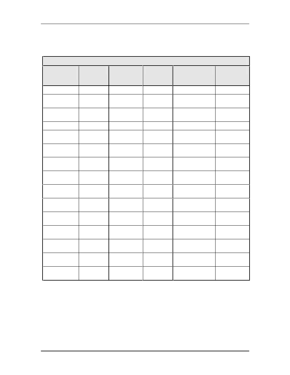
5.2.9.2 V.35 Adapter to J9
Table 5-8 provides the pinouts if the user wishes to fabricate an adapter from a 37-Pin, V.35 to J9.
Table 5-8. 25-Pin V.35 Adapter to J9
V.35 37-Pin
Connector
Signal
37-Pin
Connector
(J9)
Signal
Description
Direction
B
GND
1
GND
Signal Ground
---
C
RTS
7
RS-A
Request to Send A
(-)
Input
D
CTS
9
CS-A
Clear to Send A
(-)
Output
E
DSR
11
DM-A (DSR)
Data Mode A (-)
Output
F
RR
13
RR-A (RLSD) Receive Ready A
(-)
Output
P
SD-A
4
SD-A
Send Data A
(-)
Input
S
SD-B
22
SD-B
Send Data B
(+)
Output
R
RD-A
6
RD-A
Recieve Data A
(-)
Input
T
RD-B
24
RD-B
Receive Data B
(+)
Output
U
TT-A
17
TT-A
Terminal Timing A
(-)
Output
W
TT-B
35
TT-B
Terminal Timing B
(+)
Input
V
RT-A
8
RT-A
Receive Timing A
(-)
Output
X
RT-B
26
RT-B
Receive Timing B
(+)
Input
Y
ST-A
5
ST-A
Send Timing A
(-)
Output
AA
ST-B
23
ST-B
Send Timing B
(+)
Output