Comtech EF Data DMD2401/DMD2401L User Manual
Page 144
DMD2401/DMD2401L/DMD2401 IBS/IDR Satellite Modem
Electrical Interfaces
TM065 - Rev. 3.3
5-5
3
BAL EXC-A
External Clock A (-)
Input
21
BAL EXC-B
External Clock B (+)
Input
16
RX-0-A
Receive Octet A (-)
Output
34
RX-0 B
Receive Octet B (+)
Output
17
TT-A
Terminal Timing A (-)
Input
35
TT-B
Terminal Timing B (+)
Input
1, 19, 20, 37
GND
Signal Ground
–
*
Note: The DMD2401 Satellite Modem constantly asserts the DM/DSR Signal (DM and DSR
are actually the same signal). The modem is always in the condition of being able to
accept data. DTR Input to the modem is not necessary and is ignored. The DM/DSR
Output of the modem is located on Pins 11 and 29 as shown above.
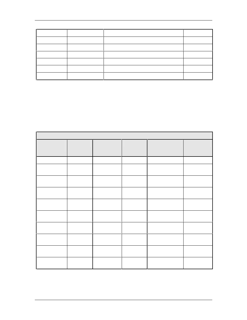
5.2.9.1 RS-232 Adapter to J9
Table 5-7 provides the pinouts if the user wishes to fabricate an adapter from a 25-Pin, RS-232 to
J9.
Table 5-7. 25-Pin RS-232 Adapter to J9
25-Pin
Connector
Signal
37-Pin
Connector
(J9)
Signal
Description
Direction
7
GND
1
GND
Signal Ground
---
4
RTS
7
RS-A
Request to Send A
(-)
Input
5
CTS
9
CS-A
Clear to Send A
(-)
Output
6
DM
11
DM-A (DSR)
Data Mode A
(-)
Output
8
RR
13
RR-A (RLSD) Receive Ready A
(-)
Output
2
SD
4
SD-A
Send Data A
(-)
Input
3
RD
6
RD-A
Receive Data A
(-)
Output
24
TT
17
TT-B
Transmit Timing A
(-)
Input
17
RT
8
RT-A
Receive Timing A
(-)
Output
15
ST
5
ST-A
Send Timing A
(-)
Output