Comtech EF Data DMD2401/DMD2401L User Manual
Page 40
DMD2401/DMD2401L/DMD2401 IBS/IDR Satellite Modem
User Interfaces
TM065 - Rev. 3.3
4-1
Section 4 – User Interfaces
4.0 User Interfaces
There are three user interfaces available for the DMD2401. These are:
1.
Front Panel
2.
Remote Port
3.
Terminal
4.1 Front Panel User Interface
The front panel of the DMD2401 allows for complete control and monitor of all DMD2401
parameters and functions via a keypad, LCD display and status LEDs.
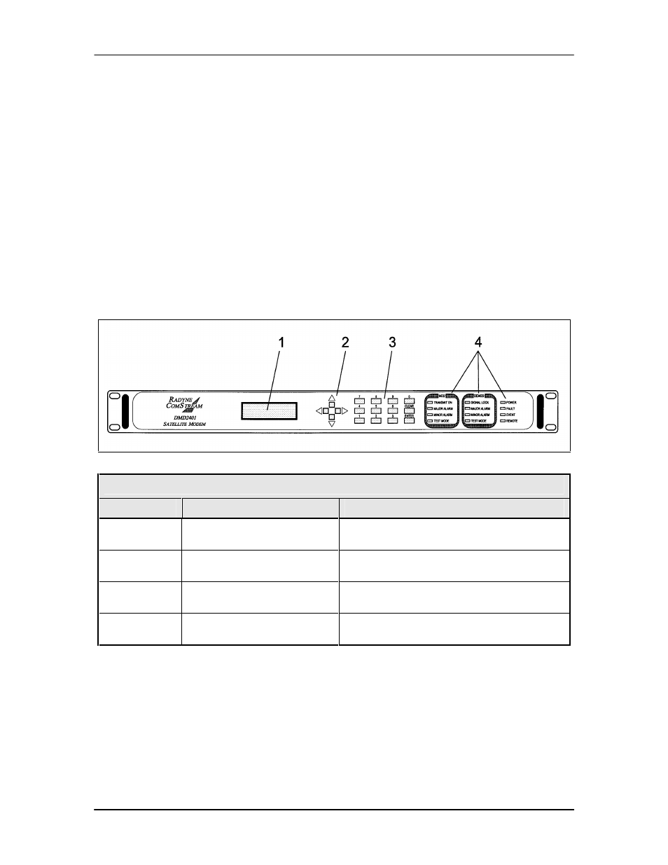
The front panel layout is shown in Figure 4-1, showing the location and labeling of the front panel.
The front panel is divided into three functional areas: the LCD Display, the Keypad, and the LED
Indicators, each described below in Table 4-1.
Figure 4-1. DMD2401 Front Panel
Table 4-1.
Item Number
Description
Function
1
LCD Front Panel Display
Displays DMD2401 Operating parameters
and Configuration data
2
Cursor Control Arrows
Controls the up, down, right and left motion
of the cursor in the LCD Display window
3
Numeric Keypad
Allows entry of numeric data and Clear and
Enter function keys
4
Front Panel LED Indicators
See Paragraph 4.1.2 below for an itemized
description of these LEDs
4.1.1 Front Panel LCD Display
The front panel display is a 2 line by 16-character LCD display. The display is lighted and the
brightness can be set to increase when the front panel is currently in use. The LCD display
automatically dims after a period of inactivity. The display has two distinct areas showing current
information. The upper area shows the current parameter being monitored, such as ‘Frequency’
or ‘Data Rate’. The lower line shows the current value of that parameter. The LCD display is a
single entry window into the large matrix of parameters that can be monitored and set from the
front panel.