Comtech EF Data DMD2401/DMD2401L User Manual
Page 147
Electrical Interfaces
DMD2401/DMD2401L/DMD2401 IBS/IDR Satellite Modem
5-8
TM065 – Rev. 3.3
5.4.6 ALARM (J6)
The modem has two Form-C Dry Contact Alarm Relays onboard and an Alarm Connector located
on the rear panel, the 9-pin male “D” sub connector (J6).
The two relays are designated Modulator Alarm and Demodulator Alarm. Non-Alarm is defined as
the powered state of the relay. Thus, if there is a Modulator Alarm and/or Demodulator Alarm, the
pins will be connected as shown in Table 5-3:
The pin definitions for J6 are shown in Table 5-4. Note that the NC and NO (Normally Closed and
Normally Open nomenclature applies to non-energized relays.
5.4.7 REMOTE (J7)
The Remote Port (J7) is the RS-485 connection for remote monitor and control of the modem. It
is a 9-Pin Female “D” Connector. Refer to Table 5-5 for the connector pinouts.
5.4.8 ASYNC DATA (J8)
The Asynchronous Data (J8) is the data interface for asynchronous data. It uses RS-232, and
RS-485 Interfaces and is a 9-Pin Female “D” Connector. Refer to Table 5-9 for the connector
pinouts. Refer to Section 5.8 for configuration switch settings.
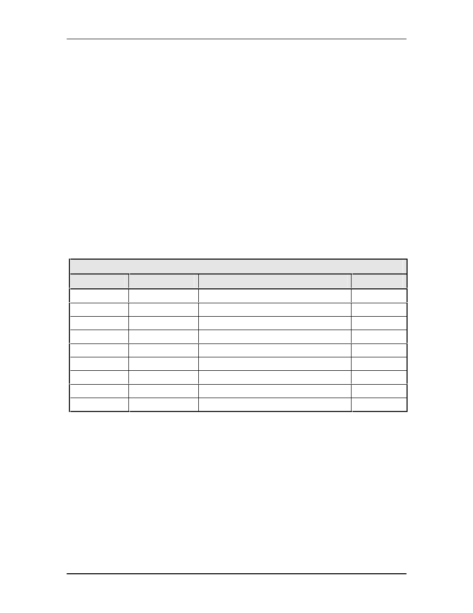
Table 5-9. Async Data Port – 9-Pin Female “D” Connector (J8)
Pin Number
Signal
Description
Direction
1
TX-485-B
Transmit Data RS-485 (+)
Input
2
TXD-232
Transmit Data RS-232
Input
3
RXD-232
Receive Data RS-232
Output
5
GND
Ground
–
4
NC
NC
–
9
RX-485-A
Receive Data RS-485 (–)
Output
8
RX-485-B/CTS
Receive Data RS-485 (+)
Output
6
TX-485-A
Transmit Data RS-485 (–)
Input
7
RTS
Request to Send
Input
5.4.9 DATA INTERFACE (J9)
The Data Interface Port (J9) is used for the Synchronous Data Interface and uses RS-422, RS-
232, and V.35 Interfaces. It is a 37-Pin Female Connector. Refer to Table 5-6 for the connector
pinouts.