6 engineering service channel (esc), 7 ibs interface connector pinouts – Comtech EF Data SDM-309B User Manual
Page 91

M&C and Interfaces
SDM-309B Satellite Modem
4-4–14
MN/U-SDM309B Rev. #
activity on either the TX Terrestrial clock or the external clock (if selected) will
substitute Satellite clock and a fault will be signaled.
4.2.1.6 Engineering Service Channel (ESC)
The engineering service channel (ESC) is fully compliant with IESS 309 Rev. 2 for serial
Data Rates as defined in Section 2.1. It generates overhead at a rate of 1/15 times the
data rate which is multiplexed with the customer data to achieve the output data rates.
Circuits included consist of a backward alarm channel and an Earth Station to Earth
Station communication channel.
The backward alarm channel is transmitted by the "near end" to inform the "far end" that
data is not being properly received. It is generated per IESS 309. Receipt of the backward
alarm is reported by closure of the secondary alarm relay.
The Earth Station to Earth Station (ES to ES) channel asynchronously samples the
Transmit Data (TD) signal of the RS-232 channel at a sample rate of 1/512 times the
customer data rate. A minimum of 3 (preferably 4) samples of each bit of the TD signal
are required to reliably reproduce the signal at the far end (RD). Therefore the maximum
RS-232 data rate which will provide for asynchronous communications is approximately
1/2000 times the customer data rate.
For example, if the modem data rate is 64 KBPS, the TD signal would be sampled at a
rate of 64000/512 which is equal to 125 BPS. The minimum of 4 samples of the TD
signal per sample rate of 125 BPS would make a maximum RS-232 data rate of 125
BPS/4 which is equal to 31.25 BPS.
If the modem data rate is 2048 KBPS, the TD signal would be sampled at 2048000/512
which is 4000 BPS. 4000 BPS/ 4 samples would require a maximum RS-232 data rate of
1000 BPS.
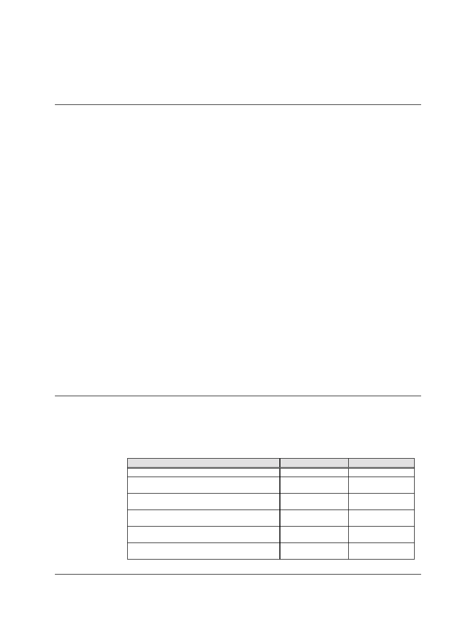
4.2.1.7 IBS Interface Connector Pinouts
The IBS interface is the Data Common Equipment (DCE), which receives incoming data,
and is provided on a 50 pin female "D" connector accessible from the rear panel of the
modem. Screw locks are provided for mechanical security of the mating connector.
Signal Function
Name
Pin Number
GROUND
GND
1,2
T1/E1 SEND DATA
T1E1_SDA
T1E1_SDB
34
18
T1/E1 RECEIVE DATA
T1E1_RDA
T1E1_RDB
36
20
EXTERNAL CLOCK IN
EXC_A
EXC_B
35
19
RS-422/V.35 SEND DATA
SD_A
SD_B
37
38
RS-422/V.35 RECEIVE DATA
RDA
RDB
39
40
