2 connector pinouts, 3 specification – Comtech EF Data SDM-309B User Manual
Page 223

External Channel Unit
SDM-309B Satellite Modem
C-C–16
MN/U-SDM309B Rev. #
2.1.2 Connector Pinouts
The RS422 and MIL-STD-188-114 interface is provided on a 37 pin female “D”
connector accessible from the rear panel of the modem. Screw locks and latching blocks
are provided for mechanical security of the mating connector.
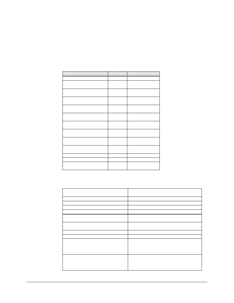
Signal Function
Name
Pin Number
SIGNAL GROUND
SG
1, 19, 20, 37
SEND DATA
SD-A
SD-B
4
22
SEND TIMING
ST-A
ST-B
5
23
RECEIVE DATA
RD-A
RD-B
6
24
REQUEST TO SEND
RS-A
RS-B
7
25
RECEIVER TIMING
RT-A
RT-B
8
26
CLEAR TO SEND
CS-A
CS-B
9
27
DATA MODE
DM-A
DM-B
11
29
RECEIVER READY
RR-A
RR-B
13
31
TERMINAL TIMING
TT-A
TT-B
17
35
MOD FAULT
_
3
DEMOD FAULT
_
21
MASTER CLOCK
(INPUT)
MC-A
MC-B
16
34
2.1.3 Specification
Circuit Supported
SD, ST, TT, RD, RT, DM, RR, MOD
FAULT, DEMOD FAULT, MC
Amplitude (RD,RT,ST,DM,RR)
4 ± 2 V differential into 100
!
DC Offset (RD, RT, ST, DM, RR)
0 ±.4 V
Impedance (RD,RT,ST,DM,RR)
Less than 100
!, differential
Impedance (SD,TT,MC)
100 ± 20
!, differential
Polarity
True when B positive wrt A
False when A positive wrt B
Phasing (RD,RT)
False to True transition of RT nominally
in center of RD data bit.
Symmetry (ST,TT,RT)
50% ± 5%
Frequency Stability (ST)
± 100 ppm
Modulator Fault
Open collector output
15 V max
20 mA max current sink
Fault is open circuit
Demodulator Fault
Open collector output
15 V max
20 mA max current sink
Fault is open circuit
