2 connector pinouts, 3 specification – Comtech EF Data SDM-309B User Manual
Page 228

SDM-309B Satellite Modem
External Channel Unit
MN/U-SDM309B Rev. #
C-C–21
2.2.2 Connector Pinouts
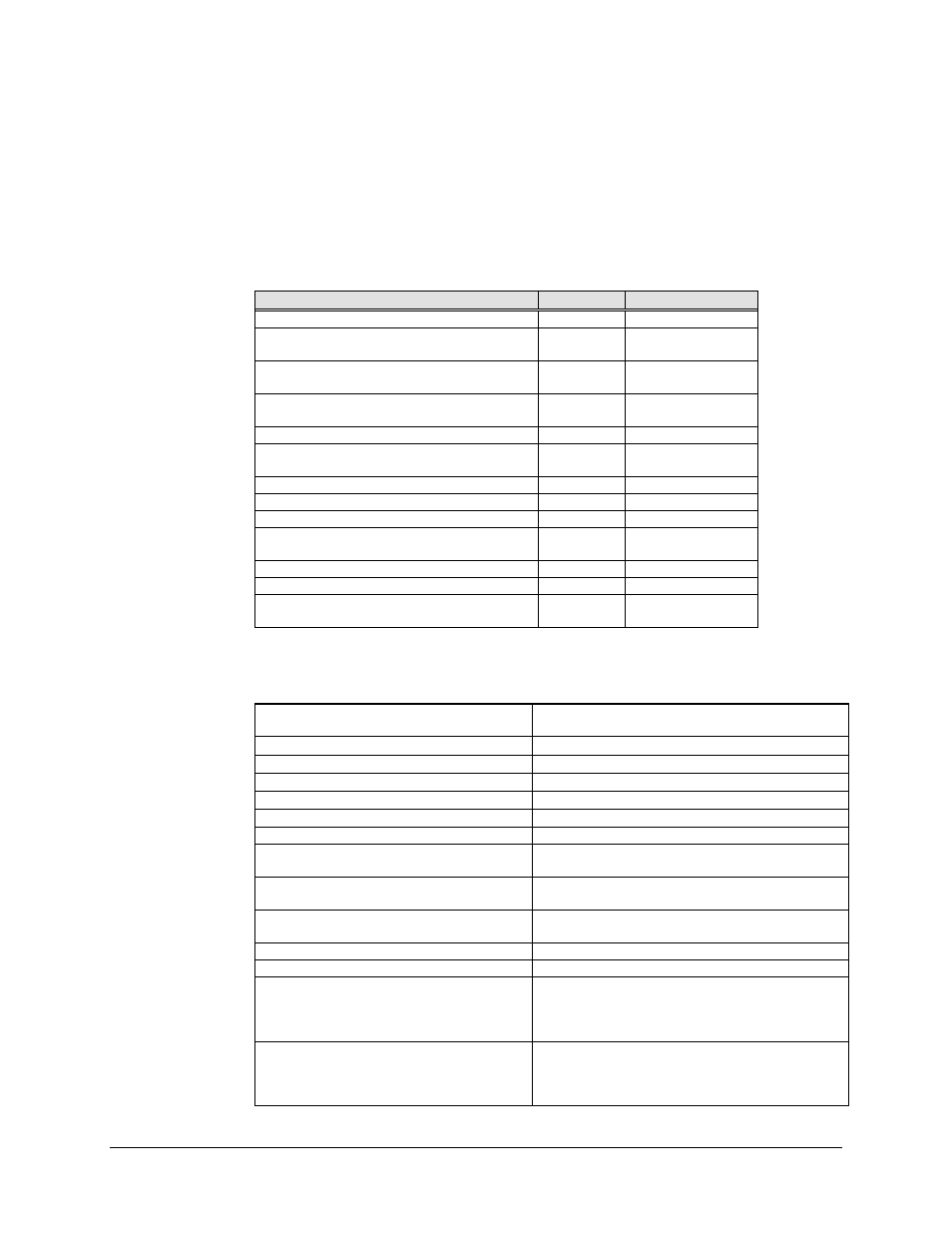
The V.35 interface is provided on the industry standard 34 pin block connector
accessible from the rear panel of the modem. Screw locks are provided for mechanical
security of the mating connector.
Signal Function
Name
Pin Number
SIGNAL GROUND
SG
A,B
SEND DATA
SD-A
SD-B
P
S
SERIAL CLOCK TRANSMIT
SCT-A
SCT-B
Y
(AA)
RECEIVE DATA
RD-A
RD-B
R
T
REQUEST TO SEND
RTS
C
SERIAL CLOCK RECEIVE
SCR-A
SCR-B
V
X
CLEAR TO SEND
CTS
D
DATA SET READY
DSR
E
RECEIVE LINE SIGNAL DETECT
RLSD
F
SERIAL CLOCK TRANSMIT EXT.
SCTE-A
SCTE-B
U
W
MODULATOR FAULT
---
(MM) m
DEMODULATOR FAULT
---
(NN) n
MASTER CLOCK
(INPUT)
MC-A
MC-B
(CC) c
(DD) d
2.2.3 Specification
Circuit Supported
SD, SCT, SCTE, RD, SCR, DSR, RLSD,
MOD, FAULT, DEMOD FAULT, MC
Amplitude (RD,SCR,SCT,SD,SCTE)
.55 V pk ± 20% differential, into 100
!
Amplitude (CTS,DSR,RLSD)
10 ± 5 V into 5000 ± 2000
!
Impedance (RD,SCR,SCT)
100 ± 20
!, differential
Impedance (SD,SCTE)
100 ± 10
!, differential
Impedance (RTS)
5000 ± 2000
!, <2500 pf
DC Offset (RD,SCR,SCT)
± .6 V max, 1000 ohm termination to ground
Polarity (SD,SCT,SCTE,RD,SCR)
True when B positive wrt A
False when A positive wrt B
Polarity (RTS,CTS,DSR,RLSD)
True when <-3V wrt ground
False when >+3V wrt ground
Phasing (SCTE,SCR)
False to True transition nominally in center of
data bit.
Symmetry (SCT,SCTE,SCR)
50% ± 5%
Frequency Stability (SCT)
± 100 ppm
Modulator Fault
Open collector output
15 V max
20 mA current sink max
Fault is open circuit
Demodulator Fault
Open collector output
15 V max
20 mA current sink max
Fault is open circuit
