3 connecting output devices, A outputs 1 ~ 8 – AGI Security GV-CONCT User Manual
Page 56
46
3.2.3 Connecting Output Devices
GV-AS400 provides up to 16 outputs. They are divided into two groups, outputs 1 ~ 8 and
outputs 9 ~16, located at opposite sides of GV-AS400. The two groups of outputs have
different absolute maximum ratings. Outputs 1 ~ 8 support the external power supply, while
outputs 1 ~ 8 only accept the internal power supply of 12V DC from GV-AS400 circuit board.
Each output has an LED indicator that turns ON to provide a visual indication that the output
device is activated.
Besides having the on-board capability of monitoring 16 outputs, GV-AS400 can be
expanded to 64 outputs if 4 units of GV-IO Boxes (16 Ports) are connected. For details, see
3.2.6 Connecting External I/O Box.
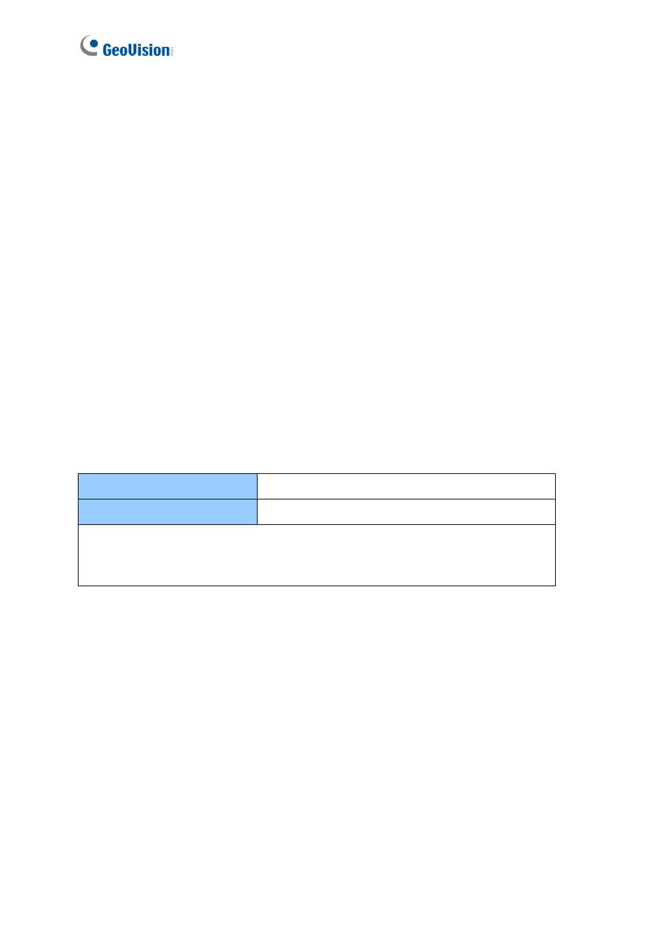
3.2.3.A Outputs 1 ~ 8
Check if your output device meets the following absolute maximum ratings before
connecting it to any of outputs 1 ~ 8.
Breakdown Voltage
277V AC, 30V DC
Continuous Load Current
5A (NO), 3A (NC)
Note: Absolute Maximum Ratings are those values beyond which damage to GV-
AS400 circuit board may occur. Continuous operation of GV-AS400 at the absolute
rating level may affect GV-AS400 reliability.