2 installation – AGI Security GV-CONCT User Manual
Page 15
GV-AS100 Controller
5
1
1.2 Installation
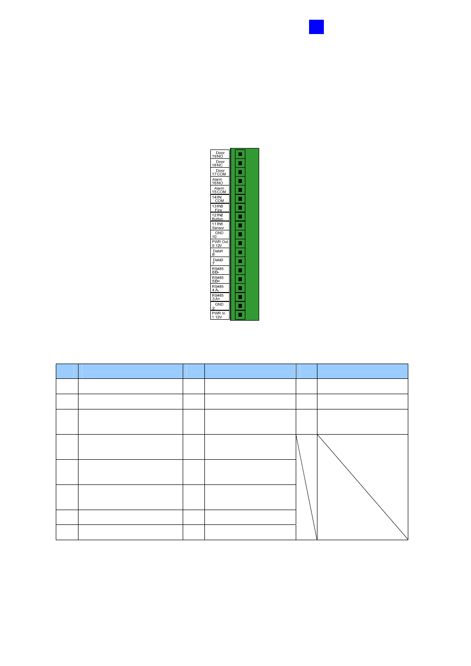
Please open GV-AS100 cabinet and wire the necessary connections to the terminal block as
illustrated below.
Figure 1-4
Pin Function
Pin Function
Pin Function
1
12V Power
9
12V Power Supply
17 Door COM
2 GND
10 GND
18
Door
NC
3
RS-485 A+ for ASBox /
ASNet or PC connection
11
Sensor IN1
19 Door NO
4
RS-485 A-for ASBox /
ASNet or PC connection
12 Button
IN2
5
RS-485 B+ for GV-
Reader connection
13 Fire
IN3
6
RS-485 B- for GV-
Reader connection
14 IN
COM
7
Wiegand Data 0
15
Alarm COM
8
Wiegand Data 1
16
Alarm NO
This manual is related to the following products: